Introduction
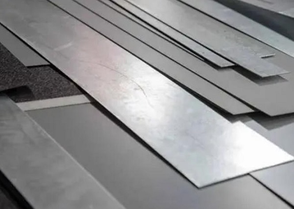
Sheet metal plays a critical role in modern manufacturing. Precision is everything when you build enclosures, automotive parts, or custom brackets. However, a major challenge in the workshop is the sheet metal gauge system. Beginners, quality inspectors, and purchasing agents often get confused by these measurements.
A common issue is assuming a specific gauge number represents the same thickness across all metals. In reality, a 16-gauge steel sheet does not have the same thickness as a 16-gauge aluminum sheet. Relying on guesswork can result in incorrect material procurement, broken tooling, and failed quality inspections.
This comprehensive guide will help you understand the sheet metal gauge chart. As an experienced product engineer at Moshijia Technology, I will explain the mechanics of these charts. You will learn how to select the correct measuring tools, follow step-by-step verification procedures, and prevent costly manufacturing errors.
What is Sheet Metal Gauge?
Definition of Sheet Metal Gauge
A sheet metal gauge is a standard unit of measurement that indicates the thickness of a metal sheet. Instead of using inches or millimeters, the industry uses a numbering system.
[High Gauge Number (e.g., 24)] ---> Means ---> [Thinner Metal Sheet]
[Low Gauge Number (e.g., 10)]  ---> Means ---> [Thicker Metal Sheet]
This system originated in the early days of industrial wire drawing and sheet rolling. Workers needed a quick, standardized way to reference material size without relying on highly sensitive measuring instruments.
Explanation of the Gauge Measurement System
The gauge system operates on an inverse scale. A higher gauge number means a thinner sheet, while a lower gauge number means a thicker sheet. For example, a 10-gauge sheet is significantly thicker than a 20-gauge sheet.
Historically, this number represented the number of times a metal sheet passed through industrial rolling mills. Each pass through the rollers squeezed the metal, making the sheet thinner. Therefore, a 24-gauge sheet underwent 24 rolling passes, making it much thinner than a sheet that only went through 10 passes.
The Gauge Measurement System
Overview of the Gauge Scale
The standard gauge scale typically ranges from 3 to 38 for industrial manufacturing applications. Most everyday sheet metal fabrication utilizes materials between 10 gauge and 26 gauge.
Understanding this scale helps you avoid major structural failures in production. Selecting a gauge that is too thin can cause your final assembly to warp under structural load. Conversely, selecting a gauge that is too thick increases material costs and adds unnecessary weight to your product.
Relationship Between Gauge Number and Thickness
The relationship between the gauge number and its actual physical thickness is non-linear. You cannot multiply or divide the numbers mathematically to determine the thickness change.
Instead, every single gauge number corresponds to a fixed decimal value in inches or millimeters. This specific value is determined by the material type. Because the system is non-linear, you must always consult an official reference chart during the design phase.
Common Materials and Their Gauge Standards
Different metals have unique physical properties, such as density and structural weight. Consequently, the manufacturing industry established distinct gauge standards for different material groups.
- Standard Steel: This standard utilizes the Manufacturers’ Standard Gage for Sheet Steel. It is based on a density of 41.82 pounds per square foot per inch of thickness.
- Galvanized Steel: This standard accounts for the additional protective zinc coating applied to the base metal. As a result, a galvanized steel sheet is slightly thicker than a standard steel sheet of the exact same gauge number.
- Stainless Steel: This standard uses the U.S. Standard Gauge system. It is calculated using a base density of 43.44 pounds per square foot per inch of thickness.
- Aluminum and Copper: Non-ferrous metals do not use the steel standards. Instead, they utilize the Brown & Sharpe (B&S) wire gauge standard, which is also known as the American Wire Gauge (AWG) system.
Understanding the Sheet Metal Gauge Chart
Explanation of the Sheet Metal Gauge Chart
A sheet metal gauge chart is an essential reference table used in machine shops worldwide. It converts abstract gauge numbers into exact, measurable physical dimensions.
The chart features columns that categorize materials by type, including steel, aluminum, and stainless steel. Each row corresponds to a specific gauge number. By reading across the row, you can find the precise thickness in inches or millimeters for your specific material.
How to Read the Chart Effectively
To read a gauge chart correctly, always identify your specific metal material first. Never look at the gauge number column without verifying the material column.
Locate your target gauge number on the left side of the chart. Next, move your eyes horizontally to the right until you reach the column matching your material. This intersection provides the exact decimal thickness you need for your design drawings or quality control checks.
Examples of Gauge Thicknesses for Different Materials
Let’s look at a practical example. A 16-gauge thickness varies significantly depending on the material you select.
- 16-Gauge Standard Steel: Measures exactly 0.0598 inches (1.519 mm).
- 16-Gauge Galvanized Steel: Measures exactly 0.0635 inches (1.612 mm).
- 16-Gauge Stainless Steel: Measures exactly 0.0625 inches (1.588 mm).
- 16-Gauge Aluminum: Measures exactly 0.0508 inches (1.290 mm).
The master reference table below outlines these variations across common manufacturing gauges:
| Gauge Number | Standard Steel (Inches / mm) | Galvanized Steel (Inches / mm) | Stainless Steel (Inches / mm) | Aluminum (Inches / mm) |
| 10 | 0.1345″ / 3.416 mm | 0.1382″ / 3.510 mm | 0.1406″ / 3.571 mm | 0.1019″ / 2.588 mm |
| 11 | 0.1196″ / 3.038 mm | 0.1233″ / 3.132 mm | 0.1250″ / 3.175 mm | 0.0907″ / 2.304 mm |
| 12 | 0.1046″ / 2.657 mm | 0.1084″ / 2.753 mm | 0.1094″ / 2.779 mm | 0.0808″ / 2.052 mm |
| 14 | 0.0747″ / 1.897 mm | 0.0785″ / 1.994 mm | 0.0781″ / 1.984 mm | 0.0641″ / 1.628 mm |
| 16 | 0.0598″ / 1.519 mm | 0.0635″ / 1.612 mm | 0.0625″ / 1.588 mm | 0.0508″ / 1.290 mm |
| 18 | 0.0478″ / 1.214 mm | 0.0516″ / 1.311 mm | 0.0500″ / 1.270 mm | 0.0403″ / 1.024 mm |
| 20 | 0.0359″ / 0.912 mm | 0.0396″ / 1.006 mm | 0.0375″ / 0.953 mm | 0.0320″ / 0.813 mm |
| 22 | 0.0299″ / 0.759 mm | 0.0336″ / 0.853 mm | 0.0313″ / 0.794 mm | 0.0253″ / 0.643 mm |
| 24 | 0.0239″ / 0.607 mm | 0.0276″ / 0.701 mm | 0.0250″ / 0.635 mm | 0.0201″ / 0.511 mm |
| 26 | 0.0179″ / 0.455 mm | 0.0217″ / 0.551 mm | 0.0188″ / 0.478 mm | 0.0159″ / 0.404 mm |
Tools Required for Measuring Sheet Metal Thickness
Overview of Measuring Tools
To verify sheet metal thickness accurately, you need the right tools. Handheld tools help you double-check incoming raw materials right on the shop floor.
                  ┌── Wheel-Style Gauge (Quick slot check on the floor)
                  │
MEASURING TOOLS ──┼── Digital Calipers (Versatile for sheet edges)
                  │
                  └── Outside Micrometer (Highest precision for flat surfaces)
The three primary options include wheel-style thickness gauges, digital calipers, and outside micrometers.
How to Use Each Tool for Accurate Measurements
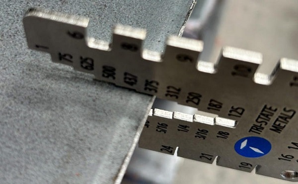
Wheel-Style Thickness Gauges
A wheel-style gauge is a circular metal disc featuring calibrated slots around its perimeter. Each slot corresponds to a specific gauge number, which is stamped directly onto the disc.
- Clean the outer edges of your metal sheet to remove any burrs, dirt, or oil.
- Slide the metal sheet edge into the slots on the tool. Do not use the large circular holes at the base of the slots; always measure using the narrow slot channel.
- Find the tightest slot that fits over the metal sheet without forcing it.
- Read the stamped gauge number next to that specific slot.
Digital Calipers
Digital calipers are highly versatile tools for measuring sheet thickness, outer dimensions, and hole depths.
- Turn on your digital caliper and thoroughly wipe the measuring jaws clean.
- Close the jaws completely and press the “Zero” button to calibrate the display.
- Open the jaws and position them perpendicular to the clean edge of the sheet metal.
- Gently close the jaws onto the metal surface. Apply light pressure to get an accurate reading without flexing the tool’s frame.
- Read the decimal value shown on the digital display screen.
Outside Micrometers
An outside micrometer is the most accurate tool for measuring flat sheet metal. It delivers ultra-precise measurements, down to a thousandth of an inch.
- Place the flat metal sheet between the polished anvil and the adjustable spindle faces.
- Turn the large thimble clockwise until the spindle approaches the metal surface.
- Switch your fingers to the small ratchet stop knob at the very end of the handle.
- Rotate the ratchet knob until it clicks three distinct times. This ensures uniform measuring pressure.
- Lock the spindle clamp lever and read the combined sleeve and thimble markings to determine your thickness.
Step-by-Step Guide to Reading Sheet Metal Gauges
Step 1: Identify the Material Type
Before taking measurements, verify the exact type of metal you are working with. Check your material tags, inventory records, or material test reports (MTR).
If the material lacks documentation, look for physical properties. Use a magnet to check for steel, inspect the surface for the dull gray zinc layer of galvanized coating, or check for the lightweight, non-magnetic traits of aluminum. Identifying the material ensures you use the correct column on your chart.
Step 2: Locate the Appropriate Gauge Chart
Once you know the material, select the corresponding gauge chart. Never use a generic sheet metal chart.
If you are inspecting an aluminum bracket, use an Aluminum Gauge Chart (AWG). If you are verifying a zinc-coated enclosure, use a Galvanized Steel Chart. Keep these charts printed and laminated at your workstation for quick access.
Step 3: Measure the Thickness Using the Right Tool
Take your physical measurement using your digital caliper or micrometer. For the most accurate results, take measurements at three distinct locations along the edge of the sheet.
Calculate the average of these three readings. This step helps account for any slight thickness variations introduced during the industrial rolling process. Record this final averaged decimal value in inches or millimeters.
Step 4: Cross-Reference with the Gauge Chart
Take your averaged decimal reading and open your material-specific gauge chart. Look down the decimal column to find the closest matching value.
[Averaged Caliper Reading: 0.0595"] ──> [Check Steel Column] ──> [Closest Value: 0.0598"] ──> [Result: 16-Gauge]
For instance, if your caliper reads 0.0595 inches on a standard steel sheet, look at the steel column. The closest value is 0.0598 inches, which means you have a 16-gauge standard steel sheet.
Common Mistakes to Avoid
Misreading the Gauge Chart
A common error is reading the wrong material column on a multi-material chart. For example, a worker might need a 14-gauge aluminum part (0.0641″) but accidentally look at the standard steel column (0.0747″). This mistake leads to buying material that is 16% too thick, which can cause assembly fit issues and unexpected weight increases.
Confusing Different Material Standards
Assuming all metals share a single gauge standard is a frequent mistake. Beginners often assume 12-gauge aluminum and 12-gauge steel are identical. However, 12-gauge steel is 0.1046 inches thick, while 12-gauge aluminum is only 0.0808 inches thick. Confusing these standards can compromise the structural integrity of your parts.
Inaccurate Measurements Due To Improper Tool Use
Using measuring tools incorrectly leads to errors. For example, forcing a wheel-style gauge onto a metal sheet can widen the slot over time, ruining the tool’s accuracy.
With digital calipers, tilting the jaws relative to the sheet edge yields a false, artificially high thickness reading. Always ensure the measuring jaws are perfectly perpendicular to the metal sheet.
Practical Applications of Sheet Metal Gauges
Importance in Manufacturing and Construction
Sheet metal gauges are critical for ensuring part compatibility and structural safety. Structural engineers calculate load ratings based on specific decimal thicknesses.
Using a sheet that is even one gauge too thin can cause a metal structure to bend or buckle under stress. In high-volume production, precise gauge control ensures consistent stamping, predictable bending, and reliable weld penetration.
Examples of Projects Requiring Precise Gauge Measurements
- Automotive Body Panels: These panels typically use 18-gauge to 20-gauge steel to balance impact resistance with fuel-efficient weight.
- HVAC Ductwork: Industrial duct ventilation systems usually rely on 22-gauge to 26-gauge galvanized steel to prevent rust and minimize resonant noise.
- Heavy Industrial Enclosures: Outdoor electronic server racks require heavy 10-gauge to 14-gauge standard steel to provide security and weather protection.
FAQ
- Why does a higher gauge number mean thinner sheet metal?The system is based on historical manufacturing steps. The gauge number originally represented the number of rolling passes required to thin the metal sheet. More passes produced a thinner sheet, resulting in a higher gauge number.
- Can I use a steel gauge chart to measure aluminum sheet thickness?No. Steel and aluminum use entirely different gauge standards. Standard steel uses the Manufacturers’ Standard Gage, while aluminum uses the Brown & Sharpe (AWG) system. Always use the chart that matches your specific material.
- How do I convert sheet metal gauge numbers to millimeters?You cannot convert gauge numbers directly using a simple mathematical formula. You must use a material-specific gauge chart to look up the exact decimal equivalent in inches, then multiply by 25.4 to convert to millimeters.
- What is the most accurate tool for measuring sheet metal gauge?An outside micrometer is the most accurate tool. It features a ratchet thimble that applies consistent measuring pressure, eliminating operator error and delivering precision down to a thousandth of an inch.
- Does the zinc coating on galvanized steel change its gauge calculation?Yes. The protective zinc coating adds physical thickness. Because of this, a galvanized steel sheet is slightly thicker than a standard raw steel sheet of the exact same gauge number.
Conclusion
Understanding how to read a sheet metal gauge chart is an essential skill for successful manufacturing projects. Misinterpreting these numbers can lead to material errors, assembly issues, and costly production delays. By identifying your material, using accurate tools like micrometers, and cross-referencing material-specific charts, you can ensure your parts meet exact design specifications every time.
Get projects quote with Moshijia Technology
Need professional sheet metal fabrication services? Moshijia Technology delivers precision-engineered parts using strict quality controls and fast turnarounds. Contact our engineering team today to receive a reliable project quote for your custom manufacturing needs.