
Copper’s role in modern manufacturing is indispensable. From the tiny electrical contacts in your smartphone to the large heat exchanger tubes in industrial plants, its superior electrical and thermal conductivity makes it a material of choice. However, machining copper on a CNC machining center presents unique hurdles. Its soft, ductile nature can lead to frustrating issues like burr formation, poor chip evacuation, and rapid tool wear. This comprehensive guide, written from the perspective of experienced product engineers and machinists, cuts through the complexity. We’ll explore which copper alloys work best for your project, how to overcome common machining challenges, optimize every parameter for precision, and ultimately control costs to deliver high-quality, functional precision copper parts.
What Makes Copper Ideal for CNC Machining?
Copper isn’t just another metal; it’s selected for its exceptional functional properties. Its primary advantage is electrical conductivity. Pure copper is the benchmark, with only silver being more conductive. This makes it non-negotiable for bus bars, electrical connectors, and RF shielding components where minimal energy loss is critical. Secondly, its thermal conductivity is outstanding, rivaled only by silver. This property is harnessed in heat sinks, cooling coils, and welding equipment to rapidly dissipate heat. Furthermore, copper offers excellent corrosion resistance, forming a protective patina that prevents further degradation, ideal for marine hardware and outdoor applications.
However, these benefits come with a trade-off: pure copper is gummy and soft. During CNC milling or turning, it tends to stick to cutting tools, generating excessive heat and creating long, stringy chips that can scratch finished surfaces and jam machinery. Understanding this duality—superior performance versus challenging machinability—is the first step to successful copper CNC machining.
Which Copper Alloys Work Best for CNC Projects?
Choosing the right alloy is the most critical decision, balancing conductivity, strength, and machinability. Here’s a detailed breakdown of the most common copper materials used in CNC shops:
| Material & Common Alloys | Key Properties | Primary Applications |
|---|---|---|
| Pure Copper (C110, C101) | Highest conductivity, excellent corrosion resistance, soft, poor machinability, prone to burrs. | Electrical bus bars, transformer windings, heat exchanger tubes, waveguides. |
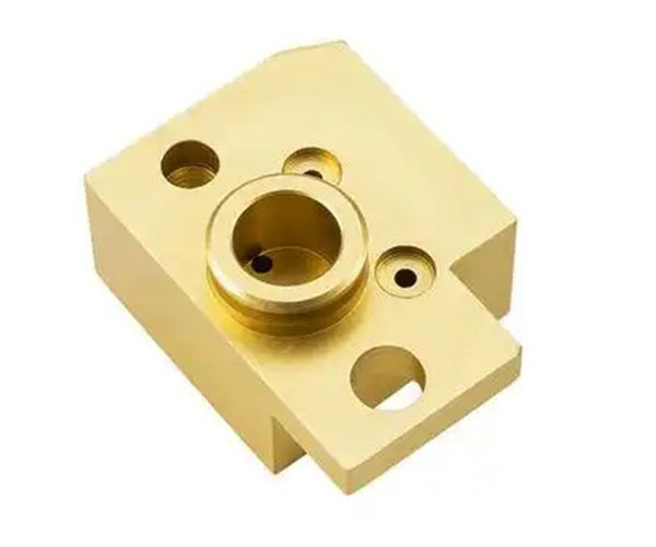
| Brass (C360, C260) | Excellent machinability, good strength, moderate conductivity, good corrosion resistance. | Precision valves, gears, plumbing fittings, musical instruments, decorative fasteners. |
| Bronze (C932, C954) | High strength, excellent wear resistance, good corrosion resistance, moderate machinability. | Bushings, bearings, pump components, marine propellers, heavy-load industrial parts. |
| Tellurium Copper (C14500) | Very high conductivity with significantly improved machinability, good strength. | Electrical switchgear, welding tips and nozzles, high-conductivity fasteners. |
| Beryllium Copper (C17200) | Very high strength & hardness, excellent fatigue resistance, non-sparking, good conductivity. | Aerospace connectors, high-performance springs, non-sparking safety tools, molds. |
- Case in Point: A client needed a complex, small-batch component for a satellite communication system. Pure copper (C101) was initially specified for maximum signal integrity. However, prototype machining resulted in severe deformation and burring, ruining the tight tolerances. We recommended switching to Tellurium Copper (C14500), which retained over 90% of the conductivity but machined cleanly, saving the project from costly scrap and rework.
What Are the Key Challenges in Machining Copper?
Success in copper CNC machining means proactively managing its inherent difficulties.
- Burr Formation: The soft material smears rather than shears cleanly, leaving raised, razor-sharp edges at exit points, especially during drilling and milling. This demands extensive deburring as a secondary operation.
- Chip Control & Evacuation: Copper generates long, continuous chips that can wrap around tools and workpieces, causing scratches on surface finish and potentially dangerous tool breakage. Effective chip evacuation strategies are mandatory.
- Workpiece Deformation: The low hardness of copper makes it susceptible to clamping forces and cutting pressures, leading to part deformation or distortion, which violates precision tolerances.
- Tool Adhesion (Built-Up Edge): Copper’s ductility causes it to weld onto the cutting tool’s edge, forming a built-up edge (BUE). This BUE changes the tool’s geometry, increases friction and heat, and degrades the machined surface quality.
How to Optimize Cutting Parameters for Copper?
Beating the challenges requires a finely tuned machining process. These parameters are your primary levers for control:
- Cutting Speed (SFM): Use high cutting speeds. This helps generate thinner chips and reduces the tendency for material to stick to the tool. For example, with carbide tools, brass (C360) can often run at 600-1000 SFM, while pure copper may require 300-500 SFM.
- Feed Rate (IPM): Employ a high feed rate per tooth. A more aggressive feed helps break chips into manageable pieces (“C” shapes or “6’s & 9’s”) rather than long strings. Do not “baby” the cut.
- Depth of Cut: Use moderate to high depth of cut (DOC). A light, skimming cut often worsens rubbing and heat generation instead of clean shearing.
- Coolant is Non-Negotiable: Always use a flood coolant. It serves three vital functions: it cools the tool and workpiece, lubricates to prevent adhesion, and forcefully flushes chips away from the cutting zone.
What Tools Are Required for Effective Copper Machining?
Tool selection directly impacts cost, quality, and cycle time.
- Tool Material: Carbide tools are the standard. They maintain hardness at the elevated temperatures generated. For high-volume production or machining highly abrasive alloys like beryllium copper, diamond-coated tools offer exceptional wear resistance and longevity.
- Tool Geometry: Opt for tools with sharp, polished cutting edges and positive rake angles. This design shears the material cleanly with less cutting force. Tools with specialized chipbreaker geometries are highly effective for managing copper chip formation.
- Tool Path Strategy: Modern CNC programming should utilize trochoidal milling or adaptive clearing paths. These strategies maintain a constant tool engagement, reducing heat and shock loads, which is crucial for preventing part deformation in thin-walled copper components.
Why Does Copper Generate So Much Heat and How to Manage It?
The primary source of heat isn’t just friction; it’s plastic deformation. As the tool shears the copper, the material deforms plastically, and a significant portion of the energy used converts directly into heat. Additionally, the high thermal conductivity of copper means heat from the cutting zone rapidly transfers into both the chip and the workpiece itself.
Managing Heat:
- Aggressive Removal: The most effective way to remove heat is to carry it away in the chips. Using the optimized high-speed, high-feed parameters ensures heat generation is localized to the shear zone and ejected with the chip.
- Flood Coolant: Directs heat away from the tool and workpiece, stabilizing the process.
- Air Blasts or Mist: For operations where liquid coolant is impractical, a directed air blast or mist system can help with chip removal and cooling.
How to Achieve a Superior Surface Finish on Copper Parts?
Achieving a mirror-like Ra value on copper is demanding but possible with a disciplined process.
- Final Pass Strategy: Use a very light finishing pass (0.001-0.003″ DOC) at a high speed with a sharp, dedicated finishing tool.
- Tool Condition: A brand new or freshly sharpened tool with a polished flute is essential. Any micro-chipping will replicate onto the surface.
- Minimize Vibration: Ensure the setup is rigid. Use fine-pitch tools for finishing to increase the number of cutting points and reduce chatter marks.
- Post-Processing: For the best results, mechanical polishing or vibratory tumbling after machining can achieve optical-quality finishes. For electrical components, a chemical passivation can remove oils and minor oxides.
What Are the Primary Applications of CNC Machined Copper?
The applications are vast and critical:
- Electrical & Electronics: Connector pins, EMI/RF shielding enclosures, circuit breaker components, waveguides, semiconductor tooling.
- Thermal Management: Heat sink bases and fins, cold plates for liquid cooling, heat exchanger plates and tubes.
- Industrial & Automotive: Bushings and bearings, valve bodies and seats, welding torch nozzles, fuel system components.
- Aerospace & Defense: High-reliability connectors, waveguide assemblies, non-sparking tools for hazardous environments.
How Does Copper Compare to Other Common CNC Metals?
| Property | Copper (e.g., C110) | Aluminum (6061) | Steel (1045) | Stainless Steel (304) |
|---|---|---|---|---|
| Conductivity | Excellent | Good | Poor | Poor |
| Machinability | Moderate (varies by alloy) | Excellent | Good | Difficult |
| Strength | Low | Moderate | High | High |
| Weight | Heavy | Light | Heavy | Heavy |
| Corrosion Resistance | Excellent | Good (with oxidation) | Poor | Excellent |
| Cost (Material) | High | Low | Low | Moderate |
Key Takeaway: Choose copper when conductivity (electrical/thermal) is the non-negotiable functional requirement. For structural parts where weight or pure machinability is key, aluminum often wins. For high-strength, wear-resistant applications, steel is superior.
What Quality Control Methods Ensure Precision?
Holding tight tolerances on copper requires anticipating its behavior.
- In-Process Inspection: Use touch probes on the CNC machining center to check critical dimensions after roughing, allowing for compensatory adjustments during the finishing pass.
- Thermal Compensation: Recognize that parts will expand during machining. Let parts cool to ambient temperature before final measurement. For precision tolerances (±0.01 mm or tighter), machining in a climate-controlled environment is advisable.
- Final Verification: Use Coordinate Measuring Machines (CMM) for complex geometries and optical comparators for detailed 2D profile inspection. Surface finish is measured with a profilometer to verify the Ra value.
How to Calculate Machining Costs for Copper Parts?
The total cost is more than material and machine time. A comprehensive quote should account for:
- Material Cost: Copper alloys, especially beryllium copper, are costlier per pound than aluminum or steel.
- Machining Time: Influenced by part complexity, required surface finish, and the alloy’s machinability rating. Brass machines quickly; pure copper takes longer.
- Tooling Consumption: The abrasive nature and gumminess of copper lead to higher tool wear costs compared to easier materials.
- Secondary Operations: Deburring, polishing, plating, or heat treatment (for beryllium copper) add significant time and cost.
- Quality Assurance: The stricter the tolerances and testing requirements (e.g., conductivity certification), the higher the cost.
Conclusion
Copper CNC machining is a specialized field that rewards expertise. The path to success lies in a strategic chain of decisions: selecting the optimal copper alloy for your functional needs, understanding and mitigating its machining challenges through precise cutting parameters and tool selection, and implementing rigorous quality control to ensure dimensional accuracy. When executed correctly, the result is a high-performance component that leverages copper’s unmatched conductive properties for demanding applications across electronics, aerospace, and industry.
FAQ
- What is the most machinable copper alloy?
Brass (C36000, “Free-Cutting Brass”) is widely considered the most machinable copper alloy. It contains lead, which acts as a chipbreaker, allowing for high-speed machining with excellent surface finishes and long tool life. - Can you achieve a mirror finish with CNC machined copper?
Yes, but it requires a meticulous process. It involves a final high-speed finishing pass with a razor-sharp, polished tool, followed by post-processing like mechanical polishing or buffing. The initial surface finish from the CNC machine is critical. - Why is my copper part deforming after machining?
This is typically due to residual stress relief or thermal expansion. The heat and pressure from machining can induce stress. As material is removed, the part warps to find a new equilibrium. Using sharp tools, ample coolant, and symmetric machining strategies minimizes this. Stress-relieving the material blank before machining can also help. - Is coolant always necessary for machining copper?
For all but the lightest cuts on small parts, yes. Flood coolant is strongly recommended to manage heat, prevent tool adhesion, and ensure effective chip evacuation. For pure copper, it is virtually mandatory. - What are the safety concerns with beryllium copper?
Beryllium copper (BeCu) is safe in solid form. However, the dust or fumes generated during machining, grinding, or welding are toxic if inhaled. Operations must use appropriate local exhaust ventilation (LEV) and personnel should wear respirators as per OSHA guidelines to prevent chronic beryllium disease.
Get a Project Quote with Moshijia Technology.
Navigating the nuances of copper CNC machining requires a partner with deep materials knowledge and precise engineering capabilities. At Moshijia Technology, we view copper not just as a stock material, but as a functional element where performance is paramount. Our experience has taught us that the “default” choice isn’t always the right one—often, a slightly different alloy or machining strategy can dramatically improve manufacturability and cost without compromising the part’s core function.
We specialize in transforming complex requirements for electrical components, thermal management systems, and high-reliability industrial parts into precision-machined realities. Our process integrates DFM feedback from the start, advanced tooling strategies, and rigorous in-process inspection to ensure your copper components meet the highest standards of quality, conductivity, and dimensional accuracy.
Let’s discuss your project. Send us your drawings or specifications, and we will provide a detailed analysis and competitive quote that reflects a true understanding of copper CNC machining challenges and solutions.