Introduction
Precision is the backbone of modern manufacturing. When standard milling or turning cannot meet tight tolerances, engineers turn to grind machining. This abrasive cutting process removes material using a rotating wheel. It achieves mirror-like surface finishes and micron-level accuracy.
However, mastering this process is challenging for beginners and junior engineers. Incorrect setups lead to costly mistakes. You might face workpiece burn, terrible surface roughness, or ruined grinding wheels.
As a product engineer at Moshijia Technology, I see these issues daily. This comprehensive guide breaks down the entire grind machining workflow. You will learn how to select equipment, set critical parameters, and troubleshoot defects. Let us dive into the mechanics of precision grinding.
Understanding Grind Machining
The Grinding Process Explained
Grind machining is a true chip-making manufacturing process. The grinding wheel contains thousands of individual abrasive grains. Each grain acts as a microscopic single-point cutting tool. As the wheel rotates at high speeds, these grains shear tiny chips from the workpiece.
The cutting mechanics involve three distinct stages:
- Plowing: The abrasive grain deforms the metal plastically, creating a groove.
- Rubbing: Friction occurs between the grain and the workpiece, generating extreme heat.
- Cutting: The grain penetrates deep enough to form a micro-chip, removing material.
Because thousands of grains cut simultaneously, grinding achieves incredible dimensional accuracy. It easily hits tolerances as tight as ± 0.0025mm– ±0.0001 inches.
Common Types of Grinding
Different part geometries require specific machine configurations. The four primary methods dominate the industrial shop floor:
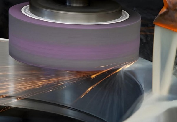
- Surface Grinding: This method creates flat surfaces. The workpiece moves back and forth on a reciprocating table under the spinning wheel.
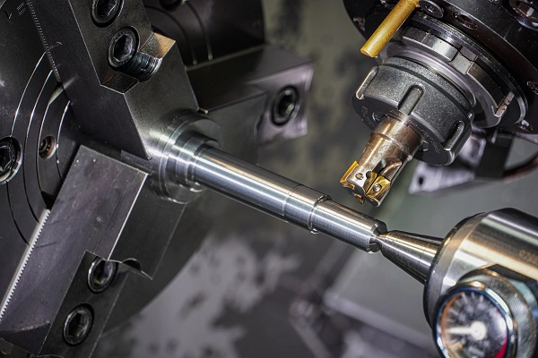
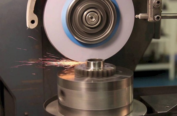
- Cylindrical Grinding: This process shapes external cylindrical surfaces. The workpiece rotates on a fixed axis while the grinding wheel moves across it.
- Centerless Grinding: This high-volume method supports cylindrical parts without using a spindle or centers. Instead, it utilizes a work-rest blade, a regulating wheel, and a grinding wheel.
- Internal Grinding: This technique finishes the inside diameters of bushings, bearings, and tubes. It requires high-speed internal grinding spindles.
| Grinding Type | Typical Geometry | Ideal Applications |
| Surface | Flat, square surfaces | Guide rails, mold plates, shim stocks |
| Cylindrical | External cylinders/tapers | Shafts, axles, test bars, pistons |
| Centerless | Mass-production cylinders | Drills, dowel pins, automotive valves |
| Internal | Inside diameters, bores | Hydraulic cylinders, gear bores, rings |
Industrial Grinding Applications
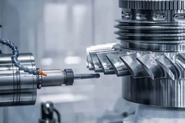
Precision grinding is vital across high-stakes industries. In aerospace manufacturing, it finishes turbine blades made of nickel-based superalloys. In the automotive sector, it finishes camshafts, crankshafts, and transmission gears to reduce friction.
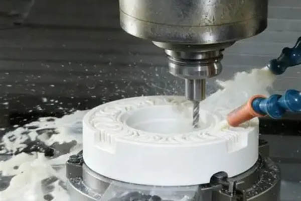
Medical device manufacturers rely on grinding for surgical instruments and orthopedic implants. Additionally, the mold and die industry uses it to achieve flawless surface finishes on hardened tool steels. Without grinding, modern high-precision machinery would not function.
Essential Grinding Equipment
Industrial Grinding Machines
A modern grinding machine must be exceptionally rigid. Heavy cast-iron bases dampen vibrations during operation. Vibration is the ultimate enemy of a smooth surface finish.
These machines use high-precision spindles to spin wheels at speeds exceeding ±30m/s. Advanced setups utilize CNC controls to manage multi-axis movements, ensuring automated accuracy down to the nanometer.
Grinding Wheel Specifications
Choosing the right grinding wheel dictates your success or failure. Wheels are categorized by five distinct parameters: abrasive type, grain size, grade, structure, and bond type.
Example Wheel Marking: A - 46 - K - 5 - V
(Abrasive) - (Grain Size) - (Grade) - (Structure) - (Bond)
- Abrasive Material: Use Aluminum Oxide (A) for steel and ferrous metals. Use Silicon Carbide (C) for cast iron, aluminum, and non-ferrous metals. For super-hard materials, choose Cubic Boron Nitride (CBN) or Diamond.
- Grain Size (Grit): Coarse grits (24 to 46) remove material quickly during roughing. Fine grits (60 to 120+) create smooth finishes during final inspection.
- Grade (Hardness): This measures how tightly the bond holds the abrasive grains. Use soft wheels (A to I) for hard materials. Use hard wheels (P to Z) for soft materials.
- Structure (Spacing): Dense structures (1 to 4) maintain form well. Open structures (8 to 16) allow excellent coolant flow and chip clearance.
- Bond Type: Vitrified bonds (V) are strong, rigid, and unaffected by water or oil. Resinoid bonds (B) offer flexibility for high-speed cutting wheels.
Crucial Machine Accessories
Precision grinding requires specialized accessories to ensure accuracy and safety:
- Magnetic Chucks: These hold ferrous parts securely without mechanical clamps, preventing part distortion.
- Wheel Dressers: Single-point or cluster diamond dressers expose sharp, fresh abrasive grains on worn wheels.
- Balancing Stands: These eliminate centrifugal forces in high-speed wheels, preventing chatter marks on parts.
Safety Precautions
Why Safety Matters
Grinding wheels spin at extreme rotational speeds, creating significant centrifugal force. A damaged or cracked wheel can explode violently, firing sharp fragments across the shop floor. Furthermore, the process generates high-heat sparks and fine respirable dust, posing severe risks to operators.
Personal Protective Equipment
Every operator must wear the correct personal protective equipment (PPE) before switching on a machine:
- Safety Glasses: Must feature side shields to deflect flying metallic sparks.
- Face Shields: Provide full-face protection against potential wheel fragmentation.
- Respirators: An N95 or rated mask blocks fine abrasive dust and mist particles.
- Hearing Protection: Earplugs or earmuffs protect against high-frequency spindle whine.
Important Safety Note: Never wear loose clothing, ties, jewelry, or woven gloves around spinning grinding wheels. They can easily catch in the spindle and pull you into the machinery.
Operational Safety Protocols
Always perform the ring test on vitrified wheels before installation. Tap the wheel gently with a non-metallic mallet. A clean, metallic ring indicates a sound structure. A dull thud means the wheel is cracked and must be discarded immediately.
Never exceed the maximum operating speed printed on the wheel label. Ensure all machine guards are locked in place before starting the spindle. Finally, stand to the side of the wheel line when starting up the machine, never directly in front of it.
Preparing for Grind Machining
Material Selection Guide
Material properties determine your grinding parameters. Hardened tool steels (above 50 HRC) grind predictably but generate significant heat. Soft aluminum Alloys tend to clog wheel pores quickly, causing loading.
When working with stainless steel, expect rapid wheel wear due to work hardening. Match your material to the correct wheel specification to prevent workpiece damage.
Setting Up the Machine
Start by cleaning the magnetic chuck thoroughly. A single trapped chip under a part can ruin your parallelism tolerances. Place the workpiece on the chuck, centering it under the wheel’s travel path. Turn on the magnet and try to move the part by hand to verify strong holding force.
Next, install the grinding wheel onto the spindle hub using a torque wrench. Mount the wheel assembly onto a balancing stand. Adjust the counterweights until the wheel rests completely still at any rotational angle. An unbalanced wheel ruins surface finishes.
Step 1: Clean Chuck Surface -> Step 2: Mount Workpiece -> Step 3: Check Magnetic Hold
Step 4: Balance Grinding Wheel -> Step 5: Mount Wheel on Spindle -> Step 6: Position Coolant Nozzles
Calibration and Testing
Mount a dial indicator on the machine spindle to verify your setup. Sweep the top surface of your workpiece to ensure it is perfectly flat and parallel to the table travel axis. Total indicator reading (TIR) should be under ±0.005 mm.
Position the coolant nozzles next. They must direct a high-pressure stream right into the cutting zone between the wheel and the part. Fluid starvation causes rapid heat buildup, leading to surface cracking.
Step-by-Step Grind Machining Process
Initial Setup and Adjustments
Turn on the machine spindle and let it idle for three minutes to reach operating temperature. Wear your safety gear and stand clear during this warmup phase. Slowly bring the wheel down until it barely touches the workpiece.
Listen for the faint “hiss” of the first abrasive grains touching the metal. Once you hear it, set your vertical dial or digital readout (DRO) to zero. This establishes your baseline reference point.
Executing the Grinding Operation
Divide your material removal into two distinct phases: roughing and finishing.
Roughing Phase: Large Infeed (0.025 mm) + Fast Cross-Feed -> Quick Material Removal
Finishing Phase: Small Infeed (0.005 mm) + Slow Cross-Feed -> Flawless Surface Quality
- The Roughing Phase: Set your downfeed (depth of cut) between ±0.020mm and ±0.040mm per pass. Use a fast table cross-feed rate to remove the bulk material efficiently. Keep a close eye on the coolant flow during heavy roughing.
- The Finishing Phase: For the final ±0.05mm of material, adjust your downfeed to a mere ±0.002 mm to ±0.005 mm per pass. Slow down the cross-feed rate to let the fine grains smooth out any peaks.
- Spark-Out Passes: Run two to three passes across the workpiece without applying any downfeed. This allows the wheel to cut any remaining micro-material caused by system deflection, achieving maximum flatness.
Real-Time Quality Monitoring
Listen closely to the acoustic feedback of the cut. A steady, rhythmic hum indicates a clean, uniform process. A harsh, screeching noise suggests your wheel is dulling or loading up with melted metal chips.
Watch the color of the sparks. Bright yellow or orange sparks mean the cutting action is clean. If sparks turn a deep red or fade out entirely while the load meter jumps, your wheel is rubbing instead of cutting. Stop the machine immediately to prevent workpiece burn.
Post-Grind Machining Procedures
Equipment Maintenance Protocols
Turn off the spindle and let the coolant drain before handling components. Wipe down the entire workspace to remove grinding sludge, which consists of fine metal particles and broken abrasive grit.
This abrasive sludge can easily score machine ways if left behind. Apply a thin layer of light way-oil to the magnetic chuck and exposed steel surfaces to prevent rust overnight.
Finished Product Inspection
Let the workpiece cool down completely to room temperature (±20 C) before taking measurements. Parts expand when heated during grinding, leading to false readings if measured hot.
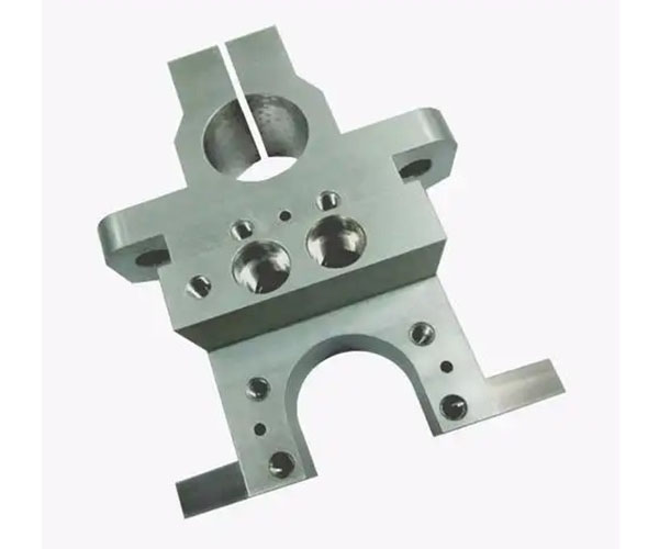
- Dimensional Inspection: Use a calibrated digital micrometer or a Coordinate Measuring Machine (CMM) to check your critical thicknesses and diameters.
- Geometric Evaluation: Place the part on a grade-A granite surface plate. Use a dial test indicator to verify flatness, parallelism, and squareness tolerances.
- Surface Finish Verification: Draw a profilometer stylus across the ground surface. For high-precision parts, ensure the arithmetic average roughness (Ra) meets your target specification, often below ±0.4 m.
Documentation and Compliance
Record all final measurements on your shop inspection report. Note the specific grinding wheel serial number, spindle speed, and coolant concentration used during production. This documentation provides traceability for ISO 9001:2015 quality control compliance.
Troubleshooting Common Grinding Issues
Identifying Workpiece Defects
Even experienced machinists run into problems. Thermal damage and structural defects can ruin parts during the final stages of production.
- Workpiece Burn: Appears as brown, blue, or black discoloration on steel parts. This indicates extreme heat has tempered and softened the metal.
- Chatter Marks: Rhythmic, wavy patterns on the ground surface. These are caused by mechanical vibrations or an out-of-round wheel.
- Wheel Loading: Occurs when soft metal chips melt and pack into the pores between abrasive grains. The wheel stops cutting and begins rubbing.
Solutions and Corrective Actions
When defects occur, systematically adjust your process parameters using this quick reference matrix:
| Observed Defect | Likely Root Cause | Immediate Corrective Action |
| Workpiece Burn | Dull wheel or low coolant flow | Dress the wheel; re-aim coolant nozzles; reduce downfeed |
| Chatter Marks | Unbalanced wheel or loose spindle | Re-balance the wheel assembly; tighten machine gibs |
| Wheel Loading | Wheel structure too dense for soft metal | Switch to a coarser grit or more open structure wheel |
| Deep Scratches | Loose grit circulating in coolant tank | Clean and flush the coolant reservoir; install a paper filter |
Preventative Strategies
Implement a strict wheel dressing schedule based on production volume. Do not wait for chatter marks to appear before dressing your wheel. Clean your coolant filtration tanks every week to remove settled magnetic fines. This regular maintenance ensures predictable finishes and extends the life of your equipment.
Conclusion
Precision grind machining requires a careful balance of machine rigidity, proper wheel selection, and precise parameter control. By following this structured workflow, you can avoid costly errors like workpiece burn and chatter marks, allowing you to achieve tight tolerances and excellent surface finishes reliably.
FAQ
What is the difference between a hard wheel and a soft wheel?
A wheel’s grade measures how tightly its bond holds the abrasive grains. A hard wheel retains its grains longer, making it ideal for soft materials. A soft wheel releases worn grains quickly, exposing fresh, sharp edges, which is necessary when grinding hard materials to prevent heat buildup.
How often should I dress a grinding wheel?
Dress your wheel whenever you notice a glazed surface, metal loading in the pores, an increase in spindle load, or a worsening surface finish. In high-precision production environments, it is best practice to dress the wheel automatically after a set number of parts.
Can I grind aluminum with a standard aluminum oxide wheel?
No, avoid using standard aluminum oxide wheels on aluminum. Soft aluminum melts and quickly clogs the wheel pores, leading to rubbing and extreme heat. Instead, use an open-structure Silicon Carbide wheel or a specialized wheel treated with wax lubricants.
What causes grinding checks or micro-cracks?
Grinding checks are tiny thermal cracks caused by excessive localized heat followed by rapid cooling. They occur when you take a depth of cut that is too deep, use an incorrect wheel grade, or provide insufficient coolant flow to the grinding zone.
Get Projects Quote with Moshijia Technology
Need high-precision ground components for your industrial projects? Moshijia Technology delivers top-tier CNC machining, surface grinding, and cylindrical grinding services. We work with tight tolerances down to ±0.002mm across various metals and ceramics. Contact Moshijia Technology today to receive a rapid, expert quote on your next project.