1. Introduction
Precision is the lifeblood of modern manufacturing. In high-stakes industries like aerospace, medical devices, and automotive engineering, the final finish determines product success or failure. Grind machining stands as the ultimate gatekeeper of this precision. It is the process that refines raw machined components into mirror-finished, ultra-tight tolerance masterpieces. However, many production floors struggle with hidden inefficiencies, sudden part rejection rates, and premature tool failure during this critical phase.
Achieving perfection in grind machining requires deep technical knowledge. It is not just about spinning a wheel against a piece of metal. It is a complex interaction of thermal dynamics, material science, and mechanical stability. When a single parameter is off, the entire batch can suffer from subsurface cracks, thermal damage, or geometric deviation. As a product engineer at Moshijia Technology, I have analyzed thousands of hours of production data to solve these exact issues.
This comprehensive guide breaks down the 7 most common mistakes in grind machining. We will explore why these errors happen, analyze their root causes, and provide actionable engineering solutions. Whether you are a machine operator, a process engineer, or a production manager, this guide will help you optimize your grinding operations, lower production costs, and achieve flawless surface integrity every single time.
2. Mistake 1: Inadequate Tool Selection
A. Importance of Choosing the Right Grinding Wheel
Selecting the correct grinding wheel is the most critical decision in any grind machining operation. A grinding wheel is a cutting tool with thousands of individual abrasive grains. The performance depends heavily on matching the abrasive type, grain size, grade, structure, and bond type to the specific workpiece material.
If you choose correctly, the wheel shears the metal cleanly, creates minimal heat, and maintains its shape for long periods. If you choose poorly, the wheel either wears down instantly or glazes over, turning your precision machine into a friction heater.
B. Consequences of Using Incorrect Tools
Using the wrong grinding wheel damages both the part and your bottom line. When a wheel is too hard for a tough material, the abrasive grains do not fracture to expose fresh, sharp edges. Instead, the grains dull and rub against the metal. This rubbing creates immense thermal energy, leading to surface burn, tensile residual stresses, and micro-cracks.
Conversely, using a wheel that is too soft causes rapid wheel breakdown. This loss of wheel geometry directly leads to dimensional inaccuracies on your workpiece, such as taper or chatter marks.
| Workpiece Material | Common Wrong Wheel Choice | Consequence | Correct Wheel Choice |
| Hardened Tool Steel (HRC 60+) | Aluminum Oxide (Hard Grade) | Wheel glazing, thermal burn, micro-cracks | Friable Aluminum Oxide or CBN (Soft/Medium Grade) |
| Carbide / Ceramics | Aluminum Oxide or Silicon Carbide | Rapid tool wear, poor surface finish | Diamond Wheel (Resin or Vitrified Bond) |
| Soft Aluminum Alloys | Tight Structure Wheel | Wheel loading (clogging), deep scratching | Open Structure Silicon Carbide Wheel |
C. Tips for Selecting Appropriate Tools
To avoid tooling errors, always follow the standard industrial selection rule: match the abrasive material to the workpiece chemistry, and match the bond hardness inversely to the material hardness. Hard materials require softer wheel grades to allow the dull abrasive grains to shed easily. Soft, ductile materials require harder wheel grades and open structures to prevent the metal chips from clogging the pores of the wheel.
Engineering Case Study: At Moshijia Technology, a client came to us because their hardened D2 steel components (HRC 62) showed severe surface burn and tiny cracks after surface grinding. They were using a standard, hard-grade aluminum oxide wheel. We switched them to a highly friable, medium-soft pink aluminum oxide wheel with a more open structure. The thermal burn disappeared instantly, wheel dressing intervals dropped by 40%, and the surface roughness ($Ra$) stabilized at a flawless 0.4 microns.
3. Mistake 2: Improper Machine Setup
A. Significance of Accurate Machine Calibration
A world-class grinding wheel cannot compensate for a poorly calibrated machine. Grind machining deals with micro-tolerances, often measuring down to single microns ($1\,\mu\text{m} = 0.00004\text{ inches}$). At this level of precision, even the slightest misalignment in the machine spindle, tailstock, or magnetic chuck amplifies into massive dimensional errors on the final product. Regular calibration ensures the mechanical axes move perfectly true to one another.
B. Common Setup Errors and Their Effects
The most frequent setup error we see on the shop floor is improper component clamping and workholding. If a workpiece is clamped with too much force, it deforms during the setup. Once the grinding process finishes and the operator releases the clamps, the part springs back to its relaxed shape, warping the ground surface.
Another major error is failing to check spindle runout. A spindle runout of just $5\,\mu\text{m}$ causes uneven wheel wear, introduces high-frequency vibrations, and leaves distinct chatter marks across the workpiece surface.
[Improper Clamping] ---> Part Deforms Under Force ---> Grinding Flattens Top Surface ---> Clamp Released ---> Part Springs Back (Warped Surface)
C. Best Practices for Machine Setup
Before you touch the grinding wheel to the workpiece, you must verify the mechanical integrity of the setup. Use a high-precision dial indicator with $1\,\mu\text{m}$ resolution to check the parallelism of the magnetic chuck relative to the wheel spindle travel. Clean the mounting surfaces thoroughly; a single stray metal chip under a workpiece can tilt it enough to ruin the parallelism.
Always use a torque wrench for mechanical clamps to ensure uniform pressure, or use specialized vacuum and magnetic chucks for delicate components to minimize distortion.
4. Mistake 3: Neglecting Workpiece Preparation
A. Importance of Proper Workpiece Cleaning and Inspection
Many grinding defects do not originate during the grinding process itself. They are born in the preceding machining steps. Grind machining is a finishing process designed to remove small amounts of material, typically between $0.1\,\text{mm}$ and $0.5\,\text{mm}$. If the workpiece enters the grinding machine with inconsistent stock allowances, heavy oil residues, or heat-treat scale, the grinding process cannot perform reliably. Clean, well-inspected blanks are mandatory for stable production.
B. Common Preparation Mistakes
The biggest mistake is ignoring the incoming stock variation from previous CNC milling or turning operations. If one part has $0.1\,\text{mm}$ of grind stock and the next part has $0.6\,\text{mm}$, the wheel will experience a sudden, massive overload on the heavier part. This overload leads to unexpected wheel breakdown, dimensional drift, and potential wheel breakage.
Additionally, leaving thick black oxide scale from heat treatment on the surface causes instant wheel loading, as the sticky scale fills the open pores of the abrasive wheel.
C. Recommended Preparation Techniques
Implement a strict pre-grind inspection protocol on your production floor. Every component must be degreased and cleaned using ultrasonic washing or industrial solvents to remove all cutting fluids and debris.
Measure incoming dimensions using calibrated micrometers to ensure the stock allowance matches the CNC grinding program parameters exactly. If parts have heavy heat-treatment scale, remove it via light shot-blasting or acid pickling before mounting them on the grinding machine.
5. Mistake 4: Incorrect Feed Rates and Speeds
A. Impact of Feed Rates on Grinding Efficiency and Quality
Finding the sweet spot for wheel speed ($v_s$), workpiece speed ($v_w$), and depth of cut ($a_e$) is a delicate balancing act. These variables dictate the material removal rate (MRR) and the chip thickness generated by each abrasive grain.
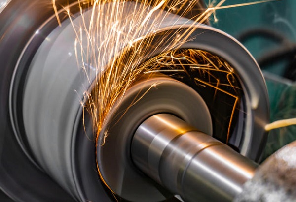
If your feed rates are too slow, the grains rub instead of cut, spiking the temperature. If your feed rates are too fast, the mechanical forces spike, which deflects the machine spindle and shatters the grinding wheel grains prematurely.
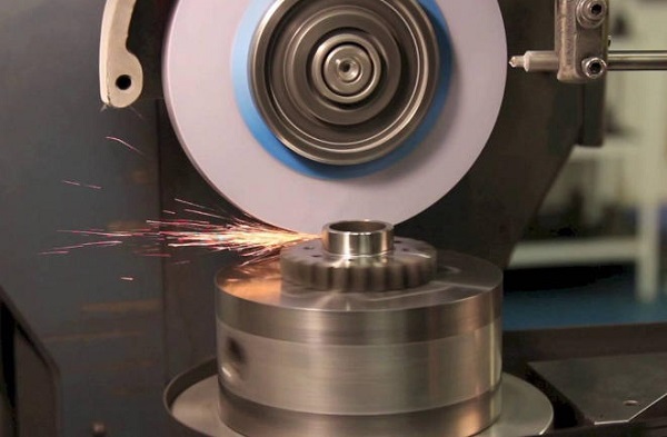
[Image demonstrating the effect of feed rates on grinding wheel chip formation]
B. Common Misconceptions About Speed Settings
A dangerous misconception on many shop floors is that “faster wheel speeds always yield a better surface finish.” While increasing the wheel speed does reduce individual chip thickness, running a wheel beyond its rated speed creates extreme friction and blocks coolant from entering the cutting zone due to the boundary layer of air around the wheel.
Another misconception is that reducing the depth of cut always prevents burning. In reality, an extremely shallow depth of cut combined with a slow feed rate often causes severe friction glazing, which triggers thermal damage.
C. Guidelines for Determining Optimal Feed Rates and Speeds
To optimize your grind machining parameters, use proven engineering calculations based on the specific material’s grinding ratio ($G$-ratio). The $G$-ratio is the volume of material removed divided by the volume of wheel worn away.
Below is a reference guide for optimal cutting speeds and feed rates across common industrial materials when using conventional vitrified wheels:
$$\text{G-ratio} = \frac{\text{Volume of Material Removed}}{\text{Volume of Wheel Wear}}$$
| Material Type | Optimal Wheel Speed (vs) | Workpiece Speed (vw) | Max Depth of Cut (ae) |
| Mild Carbon Steel | $30 – 35\,\text{m/s}$ | $15 – 25\,\text{m/min}$ | $0.030\,\text{mm/pass}$ |
| Hardened Tool Steel | $25 – 30\,\text{m/s}$ | $10 – 20\,\text{m/min}$ | $0.015\,\text{mm/pass}$ |
| Stainless Steel (300 series) | $20 – 25\,\text{m/s}$ | $12 – 18\,\text{m/min}$ | $0.010\,\text{mm/pass}$ |
| Titanium Alloys | $15 – 20\,\text{m/s}$ | $8 – 12\,\text{m/min}$ | $0.005\,\text{mm/pass}$ |
6. Mistake 5: Overlooking Coolant Usage
A. Role of Coolant in Grind Machining
Grinding generates higher specific cutting energy than almost any other machining process. Nearly $80\%$ of this energy converts into thermal energy trapped in the grinding zone.
Coolant serves three vital purposes: lubrication to reduce friction between the abrasive grains and the work, cooling to quickly carry away the generated heat, and chip flushing to wash away the fine metal dust before it clogs the wheel. Without proper coolant application, successful precision grinding is impossible.
B. Consequences of Inadequate Coolant Application
When coolant delivery fails, the results are immediate and destructive. The temperature in the cutting zone can easily exceed $1000^\circ\text{C}$ within milliseconds. This extreme heat causes thermal shock, leading to a visible blue or brown discoloration on the steel surface.
Worse than the visual color change is the underlying structural damage. The heat can cause a localized phase transformation, creating a brittle layer known as untempered martensite. This layer leads to micro-cracking and catastrophic component failure under operational stress.
Poor Coolant Delivery ---> Friction Heat Spikes to 1000°C ---> Localized Phase Transformation ---> Brittle Untempered Martensite Forms ---> Micro-cracks & Part Failure
C. Best Practices for Coolant Management
It is not just about the volume of coolant; it is about the position, pressure, and velocity of the fluid stream. The coolant nozzle must aim directly into the grinding nip—the exact point where the wheel meets the workpiece. The velocity of the fluid stream must match or exceed the tangential speed of the grinding wheel. If the coolant moves too slowly, the high-speed air barrier surrounding the spinning wheel will deflect the fluid completely away from the cutting zone.
Pro-Tip from the Shop Floor: Use a specialized coherent jet nozzle. These nozzles keep the coolant stream perfectly tight and laminar over a longer distance, breaking through the high-speed air envelope of the wheel to deliver maximum fluid straight to the grinding zone. Additionally, keep your coolant concentration monitored daily via a refractometer; maintain a stable $8\%$ to $10\%$ concentration for water-soluble oils to ensure optimal lubrication.
7. Mistake 6: Ignoring Maintenance Protocols
A. Importance of Regular Machine Maintenance
Precision grind machining requires the entire mechanical system to behave with absolute stiffness and predictability. Grinding creates an incredibly harsh environment full of highly abrasive swarf (a mixture of fine metal chips and broken grinding wheel grains). If this abrasive dust penetrates the moving parts of your machine, it degrades accuracy, creates mechanical play, and accelerates wear on the ways and ball screws.
B. Common Maintenance Oversights
The most common oversight is neglecting the condition of the dressing tool. A dull diamond dresser cannot properly dress a grinding wheel. Instead of fracturing the abrasive grains cleanly, a dull dresser crushes them, pre-glazing the wheel before it even touches a workpiece.
Another frequent maintenance mistake is ignoring spindle bearing wear. As spindle bearings wear down, they allow tiny axial and radial movements, which degrade surface finish and destroy your ability to hold tight tolerances.
Neglected Diamond Dresser ---> Crushes Wheel Grains Instead of Sharpening ---> Pre-glazed Wheel ---> High Grinding Friction ---> Surface Burn on First Pass
C. Recommended Maintenance Schedules and Practices
To maximize machine uptime and preserve micron-level precision, implement a strict preventive maintenance checklist. Treat your grinding machine like a laboratory instrument rather than a basic cutting tool.
- Daily: Check coolant refractometer levels; clean the magnetic chuck thoroughly; wipe down guideway covers to remove accumulated abrasive swarf.
- Weekly: Inspect the diamond dressing tool tip for flat spots; rotate or replace the diamond if a flat spot exceeds $0.3\,\text{mm}$; check the automatic lubrication reservoir.
- Monthly: Test the coolant filtration system; clean or replace filter paper/magnetic separators; verify spindle runout using a test arbor and dial indicator.
- Semi-Annually: Perform a complete laser alignment calibration of all machine axes; check for back-lash in the lead screws and adjust gibs if necessary.
8. Mistake 7: Failing to Monitor Process Parameters
A. Importance of Real-Time Monitoring During Grinding
In modern manufacturing, relying solely on post-process inspection is an expensive mistake. Checking the part dimensions after it leaves the machine means you only discover problems after the damage is already done. Real-time process monitoring turns grind machining from a trial-and-error guessing game into a predictable, data-driven science. It allows operators to catch deviations instantly and make adjustments before a part turns into scrap.
B. Common Parameters to Track
To truly understand what is happening inside the grinding zone, you must track more than just the final part dimensions. The two most critical indicators of grinding health are spindle motor power consumption and acoustic emission (AE) signals.
As a grinding wheel dulls or loads up with metal chips, the friction increases significantly. This friction forces the spindle motor to draw more electrical current to maintain its constant rotational speed. A sudden spike or a gradual upward trend in spindle power indicates an immediate need for wheel dressing.
Wheel Dulls / Pores Clog ---> Cutting Friction Rises ---> Spindle Motor Works Harder ---> Spindle Power Draw Spikes ---> System Signals Operator to Dress Wheel
C. Tools and Technologies for Effective Monitoring
Modern CNC grinding centers come equipped with advanced sensor integration packages. Acoustic emission sensors detect the high-frequency stress waves generated during material deformation and wheel-to-part contact. These sensors can detect “first touch” within one micron, preventing accidental crashes during rapid approach cycles.
Additionally, integrate inline touch probes inside the machine envelope to automatically measure part diameters between passes, ensuring autonomous thermal compensation.
9. Conclusion
Mastering grind machining requires a careful balance of the right tools, exact machine setup, and disciplined process control. By avoiding these 7 common mistakes—ranging from improper wheel selection to ignoring real-time monitoring—manufacturers can unlock the full potential of their grinding operations. Eliminating these errors results in immediate improvements: lower rejection rates, longer wheel life, exceptional surface finishes, and rock-solid dimensional consistency.
Precision engineering leaves no room for guesswork. Implementing these technical solutions on your shop floor protects your components from thermal damage and maximizes your production efficiency.
10. FAQ
Q1: How can I tell if my workpiece has surface burn if there is no blue discoloration?
A1: Visual inspection is unreliable for catching all types of thermal damage. Sometimes, a wheel burns the material, but the subsequent passes grind away the discolored oxide layer, leaving the underlying damaged structure hidden. To detect this, you must use non-destructive testing methods like Barkhausen Noise Analysis or a chemical nital etch test. These methods reveal localized changes in magnetic properties or microstructural hardness caused by excessive grinding heat.
Q2: What is the main difference between wheel dressing and wheel truing?
A2: Truing is the process of altering the geometric shape of the grinding wheel so that it runs perfectly concentric to the spindle axis and possesses the correct profile. Dressing is the act of removing dull abrasive grains and embedded workpiece chips from the face of the wheel. Dressing sharpens the wheel by exposing fresh, sharp abrasive crystals and restoring the open chip-clearance pores. Truing is done on new wheels, while dressing is performed repeatedly during production.
Q3: Why does my grinding wheel keep loading up when processing soft aluminum?
A3: Aluminum is highly ductile and has a low melting point. Under grinding pressures, the aluminum chips melt slightly and weld themselves into the pores of the wheel, a defect called loading. To fix this, switch to a coarse-grit, open-structure silicon carbide wheel (Structure rating 8 to 12). Also, use a heavy lubricant or a specialized straight cutting oil instead of a light water-based coolant to minimize adhesion between the aluminum and the wheel.
Q4: Can I use the same grinding wheel for both roughing and finishing passes?
A4: Yes, you can use a single wheel for both cycles by modifying your process parameters, though it requires a compromise. For the roughing pass, use a high feed rate and deep cut to maximize the material removal rate. Before starting the finishing pass, dress the wheel with a slow cross-feed to create a smooth wheel face. Then, run the finishing pass with a high wheel speed, slow feed rate, and a few “spark-out” passes (zero depth of cut) to achieve the final surface finish.
Get Projects Quote with Moshijia Technology
Need ultra-precise ground components with zero defects? Moshijia Technology specializes in high-precision grind machining, CNC milling, and complex prototype manufacturing. Our ISO 9001:2015 certified facility combines advanced real-time process monitoring with expert engineering to deliver flawless surface finishes and micron-level tolerances.