Introduction
Achieving tight tolerances and ultra-smooth finishes is a constant challenge in precision manufacturing. Traditional cutting methods like CNC turning and milling are excellent for bulk material removal. However, they often fall short when working with hardened metals or when a mirror-like finish is mandatory. This is where grind machining becomes indispensable.
As a product engineer at Moshijia Technology, I see many project managers struggle with a core issue. They do not know when to switch from conventional milling to precision grinding. Choosing the wrong process can lead to out-of-specification parts, poor surface quality, and increased production costs.
This comprehensive guide will break down the mechanics, types, and industrial applications of the grinding process. You will learn how this abrasive technology works, how to choose the right parameters, and how to apply it to your next manufacturing project.
Historical Background
Evolution of Grinding Techniques
Abrasive machining is one of the oldest manufacturing methods known to humans. Ancient civilizations used natural stones like sandstone to sharpen tools and weapons. These early methods relied entirely on manual labor and primitive mechanics. Over centuries, the process evolved from manual stone rubbing to highly mechanized industrial operations.
Key Milestones in Development
The industrial revolution changed the grinding technology landscape completely. In the late 19th century, manufacturers developed the first dedicated grinding machines. The invention of synthetic abrasives like silicon carbide in 1891 and aluminum oxide shortly after replaced natural stones. These engineered materials provided uniform hardness and predictable wear rates, which made mass production possible.
Impact of Technological Advancements
The introduction of Computer Numerical Control (CNC) systems revolutionized the field in the late 20th century. CNC grinding machines allow for automated wheel dressing, real-time tool wear compensation, and sub-micron positioning accuracy. Today, advanced sensors and automated cooling systems turn grinding from a manual art into a highly predictable digital science.
Types of Grind Machining
                  ┌───────────────────────────────┐
                  │   Types of Grind Machining    │
                  └───────────────┬───────────────┘
                                  │
         ┌────────────────────────┼────────────────────────┐
         ▼                        ▼                        ▼
┌─────────────────┐      ┌─────────────────┐      ┌─────────────────┐
│ Surface Grinding│      │Cylindrical Grind│      │Centerless Grind │
│  (Flat Planes)  │      │ (Round Profiles)│      │(No Spindle/Fix) │
└─────────────────┘      └─────────────────┘      └─────────────────┘
         │                        │
         └────────────────────────┼────────────────────────┘
                                  ▼
                       ┌────────────────────┐
                       │ Internal Grinding  │
                       │ (Bores and Holes)  │
                       └────────────────────┘
Surface Grinding
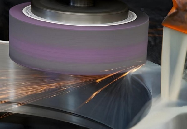
Surface grinding is the most common variant used to create flat surfaces. The machine uses a rotating abrasive wheel to remove material from a flat workpiece. The workpiece is typically secured to a magnetic chuck that moves back and forth under the spinning wheel.
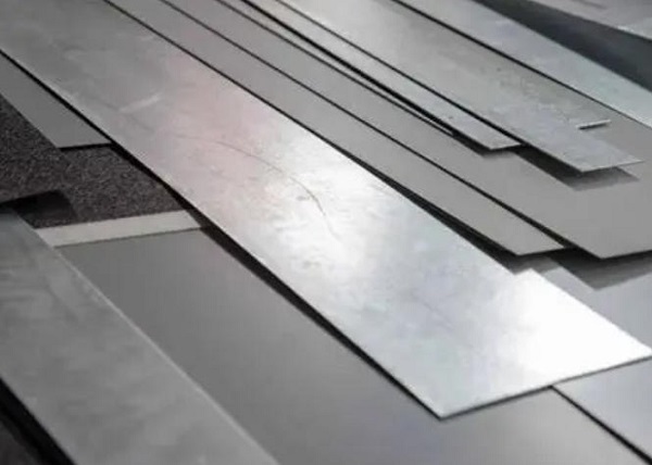
Engineers select surface grinding to achieve absolute flatness on critical reference plates, mold bases, and machine ways. In our shop, we use this method to true up heavy steel plates before pocket milling begins.
Cylindrical Grinding
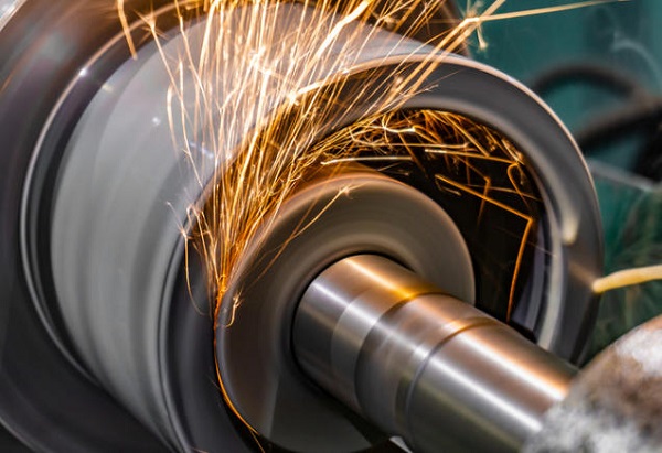
Cylindrical grinding is used to finish the outside diameters of cylindrical components. The workpiece rotates around a fixed central axis while the grinding wheel spins at a much higher speed in the opposite direction.
This process is critical for producing precision shafts, bearing journals, and automotive axles. It ensures that the outer diameter is perfectly concentric with the true rotational centerline of the part.
Centerless Grinding
Centerless grinding removes the need for center holes or fixtures to hold the workpiece. Instead, the part rests on a work-rest blade positioned between two wheels. One is a high-speed grinding wheel, and the other is a slower regulating wheel that controls workpiece rotation.
This configuration is ideal for high-volume production of long, thin parts like roller bearings, hydraulic pins, and valve stems. Because the part is fully supported along its length, it does not deflect under heavy wheel pressure.
Tool and Cutter Grinding
Tool and cutter grinding is a highly specialized process used to manufacture and sharpen cutting tools. These machines feature multi-axis articulation to ground complex geometries on end mills, drill bits, and custom reamers.
Modern tool grinders use advanced software to calculate exact relief angles and flute profiles. This ensures that the cutting tools maintain maximum sharpness and structural integrity during heavy-consuming CNC operations.
Internal Grinding
Internal grinding is designed to finish the inner surfaces of holes, bores, and tubes. A small, high-speed abrasive wheel enters the inner diameter of a rotating workpiece to remove microscopic amounts of material.
This method is vital for finishing bearing races, bushings, and aerospace sleeves. It achieves perfect roundness and tight diameter tolerances that standard drilling or boring bars cannot match.
The Grinding Process
Overview of the Grinding Cycle
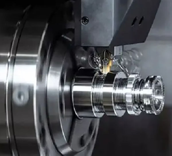
The basic grinding cycle involves bringing a high-speed abrasive wheel into controlled contact with a moving workpiece. Unlike standard milling cutters that use a distinct number of sharp edges, a grinding wheel uses millions of microscopic abrasive grains. Each individual grain acts as a tiny, single-point cutting tool that shears off a microscopic metal chip.
As the wheel feeds into the material, three distinct stages occur: rubbing, plowing, and cutting.
- Rubbing: The grain contacts the work surface, creating friction and heat but removing no material.
- Plowing: The grain deforms the metal plastically, pushing it to the sides and creating a groove.
- Cutting: The grain penetrates deep enough to overcome the material’s shear strength, throwing off a glowing chip.
Key Components Involved
Every successful grinding setup requires three primary components working in perfect harmony: the grinding machine, the grinding wheel, and the workpiece fixture. The grinding machine must possess extreme structural rigidity to dampen vibrations, as any chatter will ruin the surface finish.
The workpiece fixture, such as a magnetic chuck or vacuum plate, must lock the part in place without inducing mechanical stress or distortion.
Types of Grinding Machines
Modern shops utilize a wide range of machinery tailored to specific geometries and production volumes:
| Machine Type | Primary Axis Configuration | Common Applications | Typical Tolerance |
| Horizontal Surface Grinder | Reciprocating Table, Horizontal Spindle | Guide rails, mold plates, flat washers | $\pm 0.005 \text{ mm}$ |
| Universal Cylindrical Grinder | Rotating Headstock, Multi-Angle Bed | Precision shafts, tapered mandrels | $\pm 0.002 \text{ mm}$ |
| Thru-feed Centerless Grinder | Dual Parallel Wheels, Blade Support | Dowel pins, shock absorber rods | $\pm 0.001 \text{ mm}$ |
| 5-Axis CNC Tool Grinder | Multi-Axis Rotary and Linear Travel | Carbide end mills, custom broaches | $\pm 0.003 \text{ mm}$ |
Grinding Wheel Specifications
Composition and Materials Used
A grinding wheel consists of two primary components: the abrasive grains that do the actual cutting and the bonding agent that holds them together. Choosing the correct abrasive material depends entirely on the mechanical properties of your workpiece.
- Aluminum Oxide ($Al_2O_3$): This is the most popular choice for grinding high-tensile materials like carbon steel, alloy steel, and high-speed steel.
- Silicon Carbide ($SiC$): This material is harder but more brittle than aluminum oxide. It is ideal for low-tensile materials like gray iron, brass, aluminum, and brittle non-metals like glass or ceramics.
- Cubic Boron Nitride ($CBN$): An advanced superabrasive material. It possesses extreme thermal conductivity and hardness, making it perfect for grinding hardened tool steels and aerospace superalloys.
- Diamond: The hardest known material. Synthetic diamond wheels are used exclusively for grinding cemented carbides, ceramics, and highly abrasive composites.
Wheel Shapes and Sizes
Grinding wheels come in various standardized profiles to match different machine configurations. Straight wheels (Type 1) are standard for surface and cylindrical work. Cylinder wheels and cup wheels are popular for heavy vertical surface grinding where large surface contact areas are required. Specialized dished or sauced wheels are used primarily in the toolroom for sharpening complex gear cutters and saw blades.
Grit Size and Bonding Agents
The grit size determines the overall surface roughness and material removal rate. Grit numbers range from 10 (very coarse) to 600 or higher (ultra-fine). Coarse grits remove bulk material rapidly but leave a rough surface. Fine grits are reserved for final spark-out passes where a mirror finish is needed.
The bonding agent holds the abrasive matrix together and dictates how the wheel breaks down. Vitrified bonds are strong, rigid, and porous, making them highly resistant to oils and temperature spikes. Resinoid bonds are more shock-resistant and flexible, which makes them excellent for rough cutoff operations and high-speed hand grinding.
Factors Influencing Grind Machining
Material Properties of the Workpiece
The hardness, toughness, and thermal conductivity of the workpiece dictate how it behaves under the grinding wheel. Hardened steels grind more predictably than soft, gummy metals like pure aluminum or copper.
Soft materials tend to clog the spaces between abrasive grains, a condition known as wheel loading. Loaded wheels generate excessive heat, burn the workpiece, and cause immediate dimensional inaccuracies.
Grinding Parameters
To achieve consistent quality, engineers must carefully optimize three critical operational parameters:
$$V_w = \text{Workpiece Speed}, \quad V_s = \text{Wheel Speed}, \quad a_e = \text{Depth of Cut}$$
- Wheel Speed ($V_s$): Typically measured in surface meters per second. Running too slow causes rapid wheel wear, while running too fast causes surface burning.
- Workpiece Speed ($V_w$): Controls how fast new material feeds into the wheel. Higher speeds reduce thermal damage but increase surface roughness.
- Depth of Cut ($a_e$): The thickness of material removed in a single pass. Precision finishing passes often use a depth of cut as low as $0.002 \text{ mm}$ to prevent thermal distortion.
Cooling and Lubrication Methods
Grinding generates intense localized heat due to friction between the millions of abrasive points and the metal. Without proper cooling, surface temperatures can exceed $1000^\circ\text{C}$, leading to micro-cracking, phase transformation, and part warping.
Continuous flood cooling using synthetic or water-soluble oils is mandatory. The fluid serves three critical functions: it cools the contact zone, lubricates the grain interface to reduce friction, and flushes away loose metal swarf to prevent wheel loading.
Applications of Grind Machining
Industries Utilizing Grind Machining
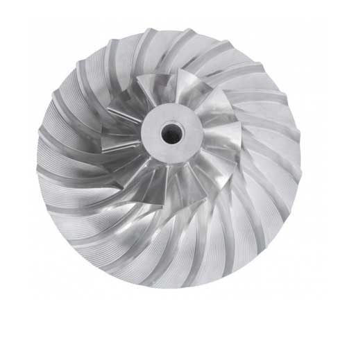
Precision grinding is a core requirement across almost all high-tech manufacturing sectors. The aerospace industry relies on it to finish turbine blade roots and landing gear struts made from tough nickel superalloys. The automotive sector uses automated grinding lines to produce millions of engine crankshafts, camshafts, and transmission gears every year.
The medical field utilizes micro-grinding to manufacture surgical tools, orthopedic implants, and hypodermic needles.
                      ┌─────────────────────────────────┐
                      │ Grinding Industrial Footprint   │
                      └────────────────┬────────────────┘
                                       │
        ┌──────────────────┬───────────┴───────────┬──────────────────┐
        ▼                  ▼                       ▼                  ▼
┌──────────────┐   ┌──────────────┐        ┌──────────────┐   ┌──────────────┐
│  Aerospace   │   │  Automotive  │        │   Medical    │   │ Die and Mold │
│Turbine Blades│   │ Crankshafts  │        │ Implants and │   │ Core Pins &  │
│& Jet Engine  │   │ & Camshafts  │        │ Tooling Pins │   │ Cavity Plates│
│  Components  │   │  Components  │        │  Components  │   │  Inserts     │
└──────────────┘   └──────────────┘        └──────────────┘   └──────────────┘
Common Products and Components
Think of any mechanical system that requires smooth, silent, and low-friction motion. It almost certainly contains ground parts. Common examples include:
- High-precision ball bearing races and ceramic balls.
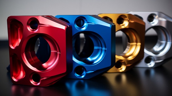
- Industrial injection mold cores, cavities, and alignment pins.
- CNC machine tool spindles and ground ball screws.
- Fuel injector nozzles and heavy-duty hydraulic pistons.
Advantages in Specific Applications
Let us consider a practical industrial example: a precision alignment pin for an automotive stamping die. The pin must have a diameter tolerance of $+0.000 / -0.002 \text{ mm}$ and a surface roughness ($R_a$) of less than $0.2 \;\mu\text{m}$. It must also be hardened to 60 HRC to withstand constant wear.
Standard carbide milling tools would struggle to cut this hardened material efficiently and would leave visible tool marks. A cylindrical grinding machine equipped with a CBN wheel can finish this pin to exact specifications in less than two minutes, achieving perfect repeatability across thousands of units.
Advantages and Disadvantages
Benefits of Grind Machining
The primary benefit of grinding is its unmatched ability to achieve extreme dimensional accuracy and superior surface finish. It can hold dimensional tolerances down to the sub-micron level ($0.0005 \text{ mm}$) with ease. Furthermore, because it cuts via microscopic abrasive points, it can machine materials of any hardness, including fully hardened tool steels, stellite, and technical structural ceramics.
Limitations and Challenges
Grinding is fundamentally a finishing operation, meaning its material removal rate is incredibly low compared to milling or turning. It is an energy-intensive process that generates high thermal loads, which requires complex fluid management systems.
The grinding wheels themselves wear down over time and require frequent dressing to restore their sharpness and geometric profile. This adds to the overall operational complexity and cost.
Comparison with Other Machining Processes
To help you select the most economical process for your project, let us compare grinding with standard CNC milling and Electrical Discharge Machining (EDM):
| Process Metric | Grind Machining | CNC Milling | EDM (Wire/Sinker) |
| Material Hardness Limit | No limit (handles $>65 \text{ HRC}$) | Typically limited to $<45 \text{ HRC}$ | Must be electrically conductive |
| Material Removal Rate | Low ($0.1 – 5 \text{ cm}^3/\text{min}$) | Very High ($50 – 500 \text{ cm}^3/\text{min}$) | Extremely Low ($0.05 – 1 \text{ cm}^3/\text{min}$) |
| Surface Finish ($R_a$) | $0.1 – 0.8 \;\mu\text{m}$ | $0.8 – 3.2 \;\mu\text{m}$ | $0.4 – 1.6 \;\mu\text{m}$ |
| Best Used For… | Final precision finishing | Rough and semi-finish shaping | Complex blind cavities or keyways |
Conclusion
Grind machining remains an essential cornerstone of modern precision engineering. While CNC milling and turning are excellent for roughing out shapes and removing bulk material quickly, grinding takes over when sub-micron tolerances and mirror-like surface finishes are mandatory. By understanding the mechanics of abrasive wheels, optimizing speeds and feeds, and managing thermal loads with proper cooling, manufacturers can produce parts that perform flawlessly under the most demanding conditions.
Selecting the right grinding strategy requires deep technical expertise, rigid machine setups, and a clear understanding of material properties. When balancing cost, speed, and precision, partnering with an experienced manufacturing team ensures your components meet specifications every single time.
FAQ
What is the difference between rough grinding and finish grinding?
Rough grinding focuses on rapid material removal with less concern for the final surface appearance. It uses coarse grit wheels, fast feed rates, and deep cuts. Finish grinding uses fine-grit wheels, slow feed rates, and tiny depths of cut to achieve the final dimensional tolerances and ultra-smooth surface finishes.
Why do grinding wheels require dressing?
During operation, abrasive grains dull over time, and microscopic metal particles can clog the wheel’s pores. Dressing is the process of using a diamond tool to strip away the worn outer layer of the wheel. This exposes fresh, sharp abrasive grains and restores the wheel’s true running shape.
Can you grind soft metals like aluminum and copper?
Yes, but it requires specialized wheels and parameters. Soft, ductile metals tend to melt and clog the wheel face very quickly, which stops the cutting action and burns the part. You must use coarse-grit silicon carbide wheels with a porous structure and abundant coolant to successfully grind these soft materials.
What causes a workpiece to burn during the grinding process?
Workpiece burn is caused by excessive heat generation in the cutting zone. This happens due to using an incorrect or dull wheel specification, insufficient coolant flow, a feed rate that is too high, or a depth of cut that is too aggressive. The burn manifests as a distinct bluish discoloration on the steel surface.
How does grinding achieve better tolerances than milling?
Milling tools experience substantial cutting forces that cause the tool and machine spindle to deflect slightly. Grinding uses thousands of microscopic points that remove tiny, dust-like chips. The individual cutting forces are exceptionally low, minimizing mechanical deflection and allowing for sub-micron accuracy.
Get projects quote with Moshijia Technology
Need high-precision ground components for your next project? Moshijia Technology offers advanced CNC surface, cylindrical, and centerless grinding services alongside our state-of-the-art CNC machining centers. Contact our engineering team today to receive a detailed technical review and a competitive production quote within 24 hours.