In the field of precision manufacturing, 5-axis CNC mill-turn machining has become a key technology in high-end industries such as aerospace, medical, and automotive with its core advantage of “completing multiple processes in one setting”. But many engineers and business owners are confused: how to truly realize its precision and efficiency potential? This article will comprehensively dismantle the core logic and practical points of 5-axis turning-mill composite from machine tool structure, tool path strategy, tool selection, precision control, industry application to automation integration.
1. Machine tool structure and axis configuration: the hardware cornerstone of precision machining
The core competitiveness of 5-axis CNC turn-mill compounding stems from its unique axis configuration design – eliminating clamping errors through multi-axis linkage and realizing integrated machining of complex parts. For experienced users, the choice of key parameters directly determines the machining limit:
- B-axis swing angle ±110°: This is one of the core linkage axes of the turning-mill composite machine, ± the swing angle range of 110° can cover the vast majority of complex surface machining needs. For example, in aero engine blade machining, the B-axis can drive the milling cutter to achieve variable angle cutting, avoiding tool and workpiece interference, and the machining efficiency is increased by more than 40% compared to traditional 3-axis machines.
- 5-axis linkage C-axis speed 3000 rpm: The C-axis acts as a rotating spindle, and the high-speed performance of 3000 rpm ensures that the turning and milling processes are synchronized. Measured by an automobile turbocharger company, when the C-axis speed is stable at 3000 rpm, the circular runout error of the impeller end face can be controlled within 0.005 mm.
- Dual spindle butt machining zero knife marks: The dual spindle design realizes “uninterrupted machining” of parts through synchronous linkage, especially suitable for long shaft parts or symmetrical structural parts. When a medical device factory processes a 500 mm long bone nail rod, it uses dual-spindle butting technology, and the surface roughness at the knife joint is Ra≤0.8 μm, which fully meets medical standards.
- Lower turret Y-axis travel ±60 mm: The addition of the Y-axis allows the turn-milling composite machine to have the ability to “turn + mill + drill”, ± the 60 mm stroke can cover most small and medium-sized parts in the radial machining needs. For example, when machining cross holes in hydraulic valve linings, the Y-axis is cooperated with the X-axis to achieve oblique hole machining, eliminating the need for secondary clamping.
- 5-axis synchronization accuracy ISO 10791-6 standard: This is the core indicator of the performance of 5-axis machines, which can control the synchronization error to within ±3 μm/m. When purchasing machine tools, an aviation parts company prioritizes ISO 10791-6 certified equipment to ensure the spatial surface accuracy of blade processing.
Practical suggestions: When selecting, it is necessary to balance the axis stroke, rotation speed and synchronization accuracy according to the maximum size, surface complexity and accuracy requirements of the machined parts – give priority to the swing angle and synchronization accuracy of the B-axis for complex curved parts, and focus on the stability of dual spindle docking for long shaft parts.
2. Tool path and CAM strategy: the core logic of intelligent machining
If the machine tool is the “body”, the tool path and CAM strategy are the “brain” – the right tool path design can maximize the potential of the machine and reduce tool loss and machining time. Senior engineers know that at the heart of toolpath optimization is “efficient cutting + error control”:
- Dynamic toolpath for turning-milling roughing: The dynamic toolpath avoids tool overload by adjusting cutting parameters (speed, feed, depth of cut) in real time. For example, when machining superalloy parts, dynamic toolpaths can automatically optimize the path based on material removal rates, resulting in 30% longer tool life and 25% shorter machining time compared to traditional fixed toolpaths.
- 5-axis linkage turning variable helical cut angle: The variable helix cut angle design reduces cutting force fluctuations, especially suitable for thin-walled parts. When processing aluminum alloy housings in an electronic equipment factory, the deformation of parts was reduced from 0.12 mm to 0.03 mm by using a variable entry angle of 15°-30°.
- Swiss Multi-Pass Synchronous G-Code: The Swiss-style machine is designed to enable “turning, milling, drilling” synchronization and customized G-code for parallel processing of multiple processes. For example, when machining micro gear shafts, the main channel is responsible for turning the outer circle, and the secondary channel is synchronously milled through the keyway, reducing the overall cycle time by 50%.
- Turn-mill residual height controlled at 0.02 mm: The residual height directly affects the surface quality of the part and the amount of subsequent machining, and the control standard of 0.02 mm can meet the polishing-free requirements of most precision parts. The residue analysis function of the CAM software optimizes the toolpath overlap rate in advance to achieve this accuracy stably.
- 5-axis simulation collision detection material removal rate: Collision is a major risk in 5-axis machining, and the collision detection function of simulation software can simulate the movement trajectory of tools, workpieces, and fixtures before machining to avoid equipment damage. A mold mill reduced the crash rate from 12% to 0.5% and increased material removal by 18%.
Practical tip: When choosing CAM software, prioritize versions that support “dynamic toolpath generation” and “5-axis simulation”, while adjusting the entry angle and feed parameters according to the part material – a small cut angle (10°-15°) is recommended for harder titanium alloys, and a large cut angle (25°-30°) for aluminum alloys.
3. Tools and cutting parameters: the key matching of efficient machining
Tools are the “teeth” of 5-axis turn-mill machining, and the choice of materials, interfaces, and cutting parameters directly determines machining efficiency, precision, and cost. The core requirement of experienced users is “accurate matching of tools and working conditions”:
| Application scenarios | Tool Material / Interface | Key cutting parameters | Advantageous performance |
| Superalloy processing | Superalloy turning-mill insert material MPcvd | Cutting speed 150-200 m/min | Hardness HRC 65+, 40% more abrasion resistance |
| Ceramic milling processing | Silicon nitride ceramic tools | The 5-axis linkage ceramic milling line speed is 800 m/min | Compared to carbide, the efficiency is 3 times higher |
| High precision milling | Turn-mill compound tool holder HSK-T63 interface | Runout error ≤ 0.002 mm | Rigid and suitable for high-speed cutting |
| Extend tool life | Microlubrication MQL 15 ml/h | Lubrication pressure 5-8 MPa | Reduce tool wear and reduce cutting temperature |
| Titanium alloy processing | Polycrystalline diamond (PCD) tools | Cutting force ≤ 500 N | Optimized for the strong viscosity of titanium alloys |
- Practical case: When an aviation enterprise machining titanium alloy blades, ordinary carbide tools were initially used, with a cutting speed of only 80 m/min and a tool life of only 2 hours. After replacing the MPcvd inserts, the cutting speed was increased to 180 m/min, the tool life was extended to 8 hours, and the cost per part was reduced by 35%.
- Key reminder: At the heart of the microlubrication MQL technology is “precise oil supply”, and the flow rate of 15 ml/h needs to be matched with the appropriate atomization pressure, otherwise it will lead to insufficient lubrication or chip adhesion – it is recommended to adjust the pressure according to the tool diameter, ≤ 5 MPa for a diameter of 10 mm and 8 MPa for a diameter of > 10 mm.
4. Precision and compensation: the core technology to ensure the quality of processing
The high-precision advantage of 5-axis turning-milling composite is inseparable from a perfect error compensation system – thermal deformation, geometric errors and other factors will affect the final accuracy, and senior users need to master the closed-loop logic of “detection-calibration-compensation”:
- 5. Real-time compensation of thermal deformation error of 5-axis turning and milling: When the machine tool is running, the temperature increase of the spindle and guide rail will lead to deformation error. Real-time data acquisition through the built-in temperature sensor, combined with dynamic compensation algorithms, can control the thermal deformation error to within ±2 μm. Actual measurements from a precision instrument factory show that after real-time compensation is turned on, the length error of long shaft parts is reduced from 0.03 mm to 0.008 mm.
- Spindle Thermal Elongation Closed-Loop Feedback ≤± 2 μm: Spindle thermal elongation is a key factor affecting machining accuracy, and the closed-loop feedback system detects the elongation amount in real time through the grating scale and automatically adjusts the Z-axis position. For example, when machining a gear shaft with a diameter of 50 mm, the thermal elongation is only 1.8 μm after the spindle runs continuously for 2 hours, which fully meets the precision requirements.
- Turn-mill composite tip following RTCP precision: RTCP (Tip Point Control) technology ensures that the tool tip always moves according to the programmed path, unaffected by B-axis wobbles. In complex surface machining, RTCP accuracy can be controlled to ±0.003 mm, which is the core guarantee for achieving high-precision surface machining.
- 5-axis geometric error 22-parameter calibration: The geometric error of the 5-axis machine involves 22 key parameters, and regular calibration by laser interferometer and ballbar can eliminate the accuracy deviation of the machine itself. It is recommended to calibrate every 3 months, especially in seasons when ambient temperatures vary greatly.
- Turning-milling center spatial error volume compensation model: This model comprehensively compensates for the linear error and angular error of the machine tool through three-dimensional spatial error analysis. After adopting this technology, the cumulative error of gear pitch of gears in gears was reduced from 0.02 mm to 0.006 mm.
Practical points: Establish a precision control system of “daily inspection – regular calibration – real-time compensation” – use a dial indicator to detect the spindle runout before processing every day, check the RTCP accuracy every week, and calibrate the geometric error every month to ensure stable accuracy.
5. Typical parts and processes: practical implementation of multi-field applications
The value of 5-axis turn-milling compounds is ultimately reflected in industry applications, where parts machining in different fields have their own unique process points, the following are the most representative examples:
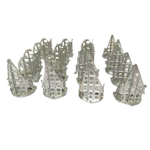
- Aero engine blade 5-axis turning and milling integrated: the blade is the core part, with complex curved surfaces and most of the materials are superalloys. Using the integrated 5-axis turning-milling process, the wheel turning, blade milling and rounding are completed in a single clamping, which improves the accuracy by 60% and shortens the machining cycle by 50% compared to traditional split machining. According to data from an aero engine factory, the blade thickness tolerance of the blade disc can be controlled as ±0.01 mm.
- Medical Bone Screw Cyclone Milling + Milling Flat Position: Bone screws require high biocompatibility and precision, using the “Cyclone Milling Thread + 5-Axis Milling Flat Position” process, the thread accuracy can reach ISO 4H level, and the flat position symmetry ≤ 0.02 mm. Through this process, the pass rate of bone screws has increased from 92% to 99.5%.
- Automobile turbocharger impeller turning-milling compound: high impeller speed and complex force, it is necessary to ensure dynamic balance accuracy. The 5-axis turning-milling process can complete impeller external turning, blade milling and balancing hole machining at the same time, with dynamic balancing accuracy reaching G2.5 level, meeting the high-speed operation needs of turbochargers.
- Hydraulic valve sleeve turning and milling cross hole without burr: The cross hole of the hydraulic valve sleeve requires no burrs, smooth inner wall, using 5-axis linkage drilling + milling process, with high-pressure cooling, it can achieve burr-free processing of cross holes, and the inner wall roughness Ra≤0.4 μm, improve the sealing of the hydraulic system.
- Rocket nozzle spiral groove 5-axis turn-milling molding: The spiral groove of the rocket nozzle directly affects the propulsion efficiency, and the 5-axis turn-milling process can accurately control the lead and depth of the spiral groove with a tolerance ≤± 0.005 mm. After adopting this process, the propulsion efficiency of the nozzle increased by 8%.
Industry Insights: Core Requirements Vary in Different Fields – Aerospace focuses on superalloy processing and surface accuracy, medical industry focuses on biocompatibility and miniaturization processing, and automotive industry pursues efficient mass production and cost control.
6. Automation and production line integration: the future trend of intelligent manufacturing
With the advancement of Industry 4.0, the automation integration of 5-axis turn-mill compounds is key to increasing productivity and stability, especially for mass production scenarios:
- 5-axis turn-milling robot loading and unloading cycle time 90 s: Robot loading and unloading can replace manual labor and achieve 24-hour continuous production. According to the production line data of an auto parts factory, the cycle time of robot loading and unloading is only 90 seconds, which is twice the efficiency compared with manual (180 seconds) and reduces human clamping errors.
- Internal vision of the turning-mill machine tool setting zero point: The in-machine vision system can automatically detect tool wear and workpiece zero point without manual intervention. After adopting this technology, the tool setting time was shortened from 3 minutes per tool to 30 seconds per handle, and the zero point repeatability was ≤± 0.002 mm.
- Digital twin visualization of 5-axis turning and milling production line: Through digital twin technology, the operating status, processing parameters and equipment load of the production line can be monitored in real time, and faults can be predicted in advance. An aviation parts production line adopted this technology, reducing equipment failure rates by 25% and increasing production plan achievement rates to 98%.
- Explosion-proof centralized chip evacuation system for turning and milling iron chips: For metal cutting operations, the stability of the chip removal system is crucial. The explosion-proof centralized chip evacuation system avoids the risk of fire caused by the accumulation of iron filings, and is especially suitable for processing flammable materials such as magnesium alloys and aluminum alloys.
- 5-axis turning-milling online measurement closed-loop compensation system: The online measurement system detects the machining accuracy in real time, and the data is fed back to the machine tool for dynamic compensation. A precision mold factory has improved the dimensional pass rate of parts from 95% to 99.8%, reducing rework costs.
Development suggestions: Small and medium-sized enterprises can start with the basic automation of “robot loading and unloading + in-machine vision tool setting” and gradually transition to the deep integration of digital twin and online measurement; large enterprises can build intelligent production lines to achieve multi-machine tool collaboration and data management.
7. Moshijia Technology’s point of view
The core value of 5-axis CNC turn-mill machining lies in “breaking process barriers and achieving the unity of precision and efficiency”. For manufacturing enterprises, if they want to maximize their potential, they should not only focus on equipment parameters, but also build a collaborative system of “machine tool-tool-tool-precision-automation” – select the appropriate axis configuration and tool according to the characteristics of the part, optimize the toolpath through CAM software, ensure accuracy with the help of compensation technology, and finally increase production capacity through automation integration. In the future, with the integration of digital twins, AI optimization and other technologies, 5-axis turning-milling compounding will develop in the direction of “higher precision, higher efficiency, and more intelligence”, becoming the core support of high-end manufacturing.
8. FAQ FAQs
- What types of parts are 5-axis CNC mill-turn-milling compounds suitable for machining?
Suitable for parts with complex surfaces, multi-process integration, and high-precision requirements, such as aero engine blades, medical bone screws, automotive turbocharger impellers, hydraulic valve sleeves, rocket nozzles, etc., it is especially suitable for mass production or high-value parts.
- How to choose the axis configuration parameters of a 5-axis mill-turn machine?
For complex curved parts, priority should be paid to the B-axis swing angle (recommended ≥± 100°) and 5-axis synchronization accuracy. long shaft parts focus on the stability of dual spindle docking; High-precision machining requires a C-axis speed of ≥2000 rpm and an RTCP accuracy of ≤±0.003 mm.
- How do tools and cutting parameters match when machining titanium alloys?
The tool can be made of MPcvd material or PCD tool, and the tool holder adopts HSK-T63 interface; The cutting speed is controlled at 150-200 m/min, the feed rate is 0.05-0.1 mm/r, and the micro-lubrication MQL (15 ml/h) reduces tool wear.
- How to Address Thermal Distortion Errors in 5-Axis Machining?
Turn on the real-time compensation function of the machine tool for thermal deformation, and regularly calibrate the thermal elongation parameters of the spindle (recommended once a week); The machine is preheated for 30 minutes before machining, and the ambient temperature is controlled at 20±2°C to avoid temperature fluctuations affecting the accuracy.
- What is the return on investment of automation integration?
The payback period for basic automation (robot loading and unloading + vision tool setting) is about 1-2 years, suitable for mass production (daily output ≥ 500 pieces); Deep integration (digital twin + in-line measurement) has a payback time of about 2-3 years, but significantly increases throughput and stability for high-value part production.