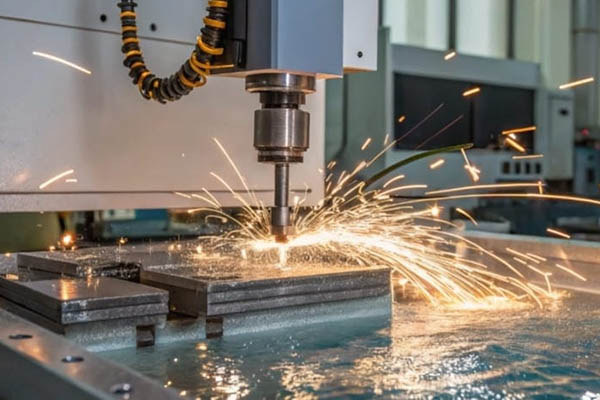
Master electric discharge machining (EDM). Learn process parameter optimization, electrode wear control, and troubleshooting for die-sinking, wire, and hole-drilling EDM.
1. How EDM and Thermal Erosion Work
Electric discharge machining (EDM) is a non-traditional manufacturing process. It shapes metal using controlled, rapid electrical sparks. Traditional machining tools physically cut away chips. EDM does not use physical force to remove material. Instead, it relies on thermal energy. This makes it perfect for hardened steel, carbide, and titanium.
[Power Source] ---> (+) Anode (Electrode/Workpiece)
                      |   <-- Dielectric Fluid (Deionized Water/Oil)
                   (-) Cathode (Electrode/Workpiece)
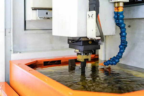
The process happens inside a liquid bath filled with a dielectric fluid. The machine places a metal electrode close to the workpiece. A small gap, called the discharge gap, remains between them. This gap usually measures between 0.005 mm and 0.5 mm. The machine then applies a high-frequency pulsating DC current.
This voltage creates an intense electrical field. As the field strengthens, the dielectric fluid breaks down. The fluid changes from an insulator to a conductor. This step is called dielectric ionization.
Once ionized, a narrow plasma channel forms. A spark jumps across the gap. The temperature of this spark reaches 8,000 to 12,000 degrees Celsius. This extreme heat instantly melts and vaporizes a tiny speck of the metal.
1. Ionization: Electrical field breaks down dielectric fluid.
2. Spark: Current flows, creating temperatures up to 12,000°C.
3. Vaporization: Metal melts and vaporizes instantly.
4. Flushing: Dielectric fluid washes away cooled metal "swarf".
When the pulse ends, the plasma channel collapses. Cool dielectric fluid rushes into the zone. The fluid cools the vaporized metal. The metal turns into tiny solid beads called EDM debris or swarf. The flowing fluid washes this debris out of the gap. This cycle repeats up to 250,000 times per second. Over time, millions of these tiny craters shape the final part.
2. Three Main EDM Types and Selection
Each EDM method fits specific shop floor challenges. Choosing the right machine saves time and money.
Die-Sinking EDM
Die-sinking EDM is also called cavity or ram EDM. It uses a custom-shaped electrode. The electrode is usually made of graphite or copper. The machine lowers this electrode vertically into the workpiece. It sinks the exact shape of the electrode into the metal.
This method is ideal for blind cavities. It is widely used in plastic injection molds, stamping dies, and blind keyways.
Wire EDM
Wire EDM uses a thin single-strand wire as its electrode. The wire typically ranges from 0.10 mm to 0.30 mm in diameter. It is made of brass or coated copper. This wire travels continuously from a supply spool to a take-up spool. This constant movement ensures a fresh, unworn cutting edge at all times.
The machine moves the wire along a 2D or 3D path. It cuts through the metal like a bandsaw. It works best for through-hole cuts, extrusion dies, tight radiuses, and prototype parts.
Hole-Drilling EDM
Hole-drilling EDM is often called spark drilling or super drilling. It uses a hollow, rotating tube electrode. The electrode is typically brass or copper. High-pressure dielectric fluid pumps directly through the center of this tube. This setup flushes debris out fast.
It is designed to drill very deep, small holes. These holes can range from 0.2 mm to 3.0 mm in diameter. The method is perfect for start holes in wire EDM, turbine blade cooling passages, and fuel injector nozzles.
       Die-Sinking                     Wire EDM                  Hole-Drilling
     +-------------+               +-------------+              +-------------+
     |  Electrode  |               |  Fine Wire  |              | Hollow Tube |
     +-------------+               +-------------+              +-------------+
            |                             |                            |
            v                             v                            v
     [Blind Cavity]                [Through Cut]                [Deep Micro-Hole]
EDM Process Comparison
Use this guide to select the right process for your application:
| Operational Feature | Die-Sinking EDM | Wire EDM | Hole-Drilling EDM |
| Primary Tooling | Custom-shaped electrode | Continuous brass wire spool | Rotating hollow tube |
| Typical Tolerances | $\pm 0.005 \text{ mm}$ | $\pm 0.002 \text{ mm}$ | $\pm 0.02 \text{ mm}$ |
| Surface Finish ($Ra$) | 0.2 to 1.6 $\mu\text{m}$ | 0.1 to 0.8 $\mu\text{m}$ | 1.6 to 3.2 $\mu\text{m}$ |
| Dielectric Medium | Hydrocarbon oil | Deionized water | Deionized water or oil |
| Best Application | Blind mold cavities, dies | Through-slots, gears, profiles | Start holes, cooling holes |
3. Optimizing Core Process Parameters
To master EDM, you must balance its process variables. Adjusting one setting always affects another.
            +-------------------------------------------+
            |          Mastering EDM Parameters         |
            +-------------------------------------------+
             /                     |                   \
            /                      |                    \
   [Pulse On-Time (Ton)]   [Pulse Off-Time (Toff)]   [Peak Current (I)]
   - Longer = Faster rough  - Longer = Stable arc     - Higher = Deep craters
   - Shorter = Fine finish  - Shorter = Fast cut      - Lower = Low wear
Pulse On-Time ($T_{\text{on}}$)
This is the duration of the spark, measured in microseconds ($\mu\text{s}$). A longer pulse on-time delivers more thermal energy. This increases the material removal rate (MRR) and creates larger, deeper craters. However, it results in a rougher surface finish.
If your pulse is too long, the electrode wears down faster. For roughing steel, set $T_{\text{on}}$ between 50 $\mu\text{s}$ and 150 $\mu\text{s}$. For finishing cuts, lower it to 1 $\mu\text{s}$ to 10 $\mu\text{s}$.
Pulse Off-Time ($T_{\text{off}}$)
This is the pause between sparks, also measured in microseconds. This pause is crucial because it allows the dielectric fluid to cool the discharge gap. It also gives the fluid time to flush out the vaporized metal debris.
If your $T_{\text{off}}$ is too short, debris builds up in the gap. This leads to DC arcing, which can ruin your workpiece. If $T_{\text{off}}$ is too long, you waste valuable machining time. A good rule of thumb is to set $T_{\text{off}}$ to 10% to 30% of your $T_{\text{on}}$ value during stable cuts.
Peak Current ($I$)
Peak current is the maximum amperage delivered during each spark. Higher current makes sparks hotter and larger. This speeds up material removal, but it also increases surface roughness ($Ra$).
Keep current low during delicate finishing passes. For roughing large areas, use higher current. Always match your current to the surface area of your electrode to avoid overloading the cut.
Spark Gap (Voltage)
The machine’s CNC controller monitors the average gap voltage. This voltage controls the physical distance between the electrode and your workpiece. If the gap is too narrow, the electrode short-circuits against the workpiece. If the gap is too wide, no spark can cross.
A stable machining gap usually sits between 20V and 60V. Modern machines adjust the servo feed rate automatically to keep this gap constant.
Dielectric Pressure
Dielectric flushing is the unsung hero of EDM. Debris left in the gap acts as a bridge, causing unstable, destructive arcs. You can flush the gap using pressure, suction, or by pulsing the electrode up and down.
For deep cavities, use intermittent jet flushing at 0.5 to 1.5 bar. Be careful: too much pressure can deflect thin wire electrodes or small rod tools.
4. Selecting Electrode Materials and Controlling Wear
Electrode wear is a constant challenge. If your electrode deforms, your finished part will be inaccurate.
                     +---------------------------+
                     |  Electrode Material Match  |
                     +---------------------------+
                      /                         \
         [Graphite Electrode]              [Copper Electrode]
         - Best for steel roughing         - Best for fine detail
         - High material removal rate      - Mirror finishes (Ra < 0.2 um)
         - Easy to CNC machine             - High wear resistance
Graphite vs. Copper
- Graphite: This is the industry standard for die-sinking EDM. It is highly resistant to heat and does not melt. Instead, it turns directly into gas at extreme temperatures. This properties give it a high material removal rate. It is also easy to machine on a CNC mill.Use fine-grained graphite (particle size under 5 microns) for detailed work. Use medium-grained graphite for fast, heavy roughing.
- Copper: Copper conducts electricity and heat exceptionally well. It is highly ductile, meaning it does not chip easily. Copper is perfect for creating mirror finishes with $Ra$ values under 0.2 $\mu\text{s}$.It is also the best choice for machining carbide or tungsten. Copper electrodes can be drawn into very thin wires or complex, delicate shapes.
Electrode Wear Ratio
The electrode wear ratio (EWR) measures how much electrode material is lost compared to the volume of metal removed from the workpiece:
$$\text{EWR} = \left( \frac{\text{Volume of Electrode Wear}}{\text{Volume of Workpiece Material Removed}} \right) \times 100\%$$
In roughing operations, you should target an EWR under 1%. During finishing, this ratio can rise to 10% or higher.
Wear Reduction Strategy
To keep electrode wear as low as possible, apply these shop floor tactics:
- Use Positive Polarity: Set your electrode as the positive anode (+) and the steel workpiece as the negative cathode (-). This setup works best when using pulse on-times longer than 20 $\mu\text{s}$. The heavy positive ions strike the workpiece, while lighter electrons strike the electrode. This protects your tool from excessive wear.
- Build Carbon Protection: During the cut, hydrocarbons in the dielectric oil crack. This leaves a thin, protective layer of carbon soot on the electrode’s surface. You can encourage this by using longer pulse times and maintaining a stable spark gap.
- Multi-Electrode Process: Never try to rough and finish a cavity with a single electrode. Use a dedicated roughing electrode to remove 90% of the material. Then, switch to a fresh finishing electrode to cut the final details.
5. Achieving High Surface Quality and Tolerances
EDM is a thermal process, meaning it leaves a heat-affected zone on the metal. Understanding this layer is key to achieving tight tolerances.
[  Recast Layer (White Layer)  ]  <-- Hard, brittle (Micro-cracks)
---------------------------------
[ Heat-Affected Zone (HAZ)     ]  <-- Tempered, modified microstructure
---------------------------------
[ Unaffected Base Metal        ]  <-- Original steel properties
The Recast Layer
Every EDM spark melts a tiny pool of metal. When the spark ends, the dielectric fluid chills this remaining pool instantly. This rapid cooling creates a hard, brittle outer crust called the recast layer or “white layer.”
This layer is highly stressed and filled with microscopic cracks. Beneath it lies the heat-affected zone (HAZ), where the metal’s grain structure has been altered by heat.
Eliminating Cracks
To prevent part failure from micro-cracks, you must manage this recast layer:
- Step Down Parameters: Gradually reduce your pulse energy across multiple passes. In wire EDM, use one high-power roughing cut followed by three or four low-power skim cuts. Each skim pass gently removes the brittle recast layer left by the previous cut.
- Polish and Temper: For critical aerospace or medical parts, polish away the recast layer using abrasive pastes or chemical etching. Baking the parts in an oven (tempering) also helps relieve internal stresses.
Managing Oversize
An EDM spark always cuts a path slightly wider than the electrode itself. This difference is called discharge oversize or spark allowance.
                       |<-- Electrode Width -->|
                       |                       |
   [Workpiece] =======|   ( Spark Gap )       |======= [Workpiece]
                      |<------- Cut Width ------>|
If your electrode is 10.00 mm wide and your spark gap is 0.05 mm, the finished slot will measure 10.10 mm. To compensate, always subtract this spark gap value from your electrode design dimensions.
6. Troubleshooting Common EDM Defects
Even experienced machinists run into EDM issues. Use this quick reference guide to identify and fix common problems on your shop floor.
       [Unstable Arcing?]                    [Poor Surface Finish?]
               |                                       |
       +-------+-------+                       +-------+-------+
       |               |                       |               |
[Increase Toff] [Check Flushing]         [Reduce Ton]    [Lower Current]
Problem: DC Arcing (Localized Burning)
- Visual Clues: A steady yellow spark appears instead of a blue-white flash. Pitch-black carbon spots form on the workpiece.
- Root Causes: Heavy debris accumulation in the gap, insufficient pulse off-time, or poor dielectric flushing.
- Practical Fixes:
- Increase your pulse off-time ($T_{\text{off}}$) by 20%.
- Increase dielectric flushing pressure.
- Program periodic electrode retraction jumps to clear out debris.
Problem: Excessive Electrode Wear
- Visual Clues: Corners of your electrode rounded off too quickly. Depths of cavities are shallower than programmed.
- Root Causes: Wrong polarity setting, pulse on-time ($T_{\text{on}}$) is too short for the current used, or poor electrode material.
- Practical Fixes:
- Verify your machine polarity (switch electrode to positive for roughing steel).
- Increase your pulse on-time.
- Switch to a higher-density, smaller grain-size graphite.
Problem: Poor Surface Finish
- Visual Clues: Pitted, rough surface with visible craters.
- Root Causes: Peak current ($I$) is set too high, or pulse on-time ($T_{\text{on}}$) is too long.
- Practical Fixes:
- Reduce both peak current and pulse on-time.
- Run multi-pass skim cuts (for wire EDM).
- Increase your dielectric fluid filtration rate to remove reflective suspended particles.
7. Advanced Materials and Complex Cavities
Machining exotic alloys requires specialized strategies to maintain speed and quality.
Carbide Machining
Tungsten carbide is exceptionally hard and brittle. It does not conduct electricity as well as copper or steel. Because of this, standard steel parameters will cause micro-cracking and cobalt depletion.
- The Fix: Use copper-tungsten (CuW) electrodes. This material resists wear from hard carbides. Set the machine to negative polarity on the electrode. Keep pulse on-times very short (under 5 $\mu\text{s}$) to avoid deep heat penetration. Use high-frequency pulsing to prevent thermal shock.
Titanium Alloys
Titanium (like Ti-6Al-4V) has low thermal conductivity. It tends to hold onto heat rather than dissipating it. This can lead to localized overheating and gas pockets in the discharge gap.
- The Fix: Increase your pulse off-time ($T_{\text{off}}$) to give the titanium more time to cool between sparks. Use high-pressure flushing to sweep away sticky titanium debris. Adding a rotary axis to spin your electrode helps distribute heat evenly and improves flushing.
Deep Mold Cavities
Deep, narrow ribs are the ultimate test for die-sinking EDM. Debris naturally gets trapped at the bottom of these narrow pockets, leading to arcing.
      [Electrode]  <-- Rib electrode
         |   |
         |   |     <-- Trapped debris cannot escape
    +----+   +----+
    | Workpiece   |
    +-------------+
- The Fix: Design your electrode with internal flushing holes so fluid can pump directly into the cut. Use a high-frequency jump cycle. Program the CNC machine to retract the electrode rapidly every few seconds. This pumping action sucks fresh dielectric fluid down into the deep cavity, keeping the process stable.
8. EDM Best Practices FAQ
How do I choose between oil and water as a dielectric fluid?
Use hydrocarbon oil for die-sinking EDM. Oil creates a smaller spark gap, which delivers sharper corners and a smoother surface finish. Use deionized water for wire EDM and hole-drilling. Water cools the wire quickly and flushes high volumes of debris out of deep, open cuts.
Why is my wire EDM brass wire breaking constantly during cuts?
Wire breakage is usually caused by physical contact with the workpiece or high thermal tension. To fix this, increase your pulse off-time ($T_{\text{off}}$) to cool the wire, or reduce your wire tension setting. Make sure your flush nozzles are close to the workpiece to prevent dry-cutting zones.
What is the minimum corner radius I can achieve using wire EDM?
Your minimum corner radius is limited by the radius of your wire plus the spark gap allowance. If you use a standard 0.25 mm diameter wire with a 0.02 mm spark gap, your minimum inside corner radius will be roughly 0.145 mm. For tighter corners, switch to a micro-wire setup (0.10 mm or smaller).
How does workpiece hardness affect EDM cutting speed?
Unlike milling or turning, metal hardness does not affect EDM speed. EDM removes material through thermal melting, not mechanical shearing. A block of hardened tool steel (62 HRC) cuts at almost the exact same speed as a block of annealed steel (20 HRC).
Get Projects Quote with Moshijia Technology
Need high-precision EDM parts? Moshijia Technology offers premium CNC machining, precision die-sinking, and multi-axis wire EDM services. Our advanced machinery easily handles complex geometries, tight tolerances, and hard metals. Contact us today to request a rapid quote for your prototyping and production runs!