Introduction
The gap between a standard machinist and a precision specialist is measured in microns, not millimeters. Precision machining isn’t about buying a more expensive CNC machine; it’s a systematic discipline. We define it as the consistent ability to produce parts that hold a tolerance grade of IT6 to IT7 and a surface finish of Ra 0.8 µm or better. This isn’t a goal; it’s a standard. As an engineer at Moshijia Technology, I’ve seen shops scrap thousands of dollars in aerospace aluminum because they missed one critical step in the thermal compensation chain. This guide will walk you through an end-to-end, skill-building workflow. We will move from blueprint analysis to final inspection, solving the core problems of dimensional drift, poor surface quality, and high scrap rates at their root.
What Is the Real Goal of Blueprint Analysis?
Before a single chip is cut, your precision battle is won or lost at the drawing board. The goal is not just to read a drawing, but to mentally machine the part, identifying every trap that can kill your tolerance.
Decoding Datums & Critical Features
The foundation of your entire setup lies in the datum targets. A classic rookie mistake is accepting a standard datum structure without questioning its functional intent. Ask yourself: does the datum order on the drawing match how the part actually functions in an assembly? A surface profile callout of 0.01 mm next to a theoretical sharp corner might actually require you to hold that surface in a single clamping. If you split it across two setups, you are stacking the flatness error of your fixture and the machine’s volumetric inaccuracy. We resolve this by using a Coordinate Measuring Machine (CMM) to qualify the fixture’s location pins relative to the machine’s origin before clamping, ensuring your physical setup matches the theoretical datum simulation.
The Material Condition Trap
Do not just scan the title block. Analyze every modifier. A part with a true position tolerance of 0.005 mm at MMC (Maximum Material Condition) is a different beast than one at RFS (Regardless of Feature Size). For a precision bore with an MMC callout, you gain bonus tolerance as the hole gets larger. This changes your process strategy—you might intentionally target the upper size limit of a hole to ease the position constraint, turning a scrapped part into a conforming one. This is the kind of strategic thinking that separates operators from process engineers. Always highlight the critical-to-function dimensions and map them directly to a specific machining operation and tool number.
How to Select Materials and Machines for Accuracy?
Choosing the right steel is one thing. Choosing it for consistent, predictable removal is another. The material dictates the machine’s personality; ignoring this synergy is the direct cause of random chatter and tool failure.
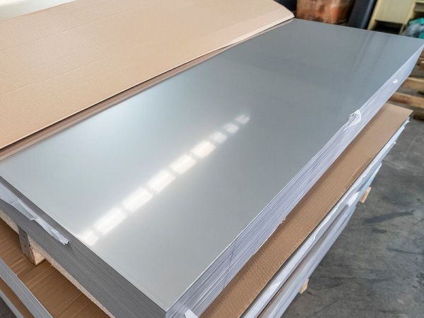
Material Stability and Internal Stress
Let’s talk about pre-hardened 4140 steel versus a generic hot-rolled low-carbon steel. The 4140 is ultrasonic tested and stress-relieved. Why does this matter for precision? When you remove 70% of the material volume from a rolled bar, you unleash internal stresses that can warp the part by 0.1 mm over several hours, long after it leaves the machine. We always specify a roughing operation, leaving 0.25 mm of stock, followed by a low-temperature stress-relieving cycle at 180°C for 4 hours before the finishing pass. For your machine tool selection, do not fall for the “ISO 230-2 accuracy” alone. A machine that passes static tests can still fail dynamically. We look for machines with linear glass scales with 0.1 µm resolution and pitch error compensation tables built into the CNC controller. This hardware blocks the leadscrew heating error before it even reaches your part.
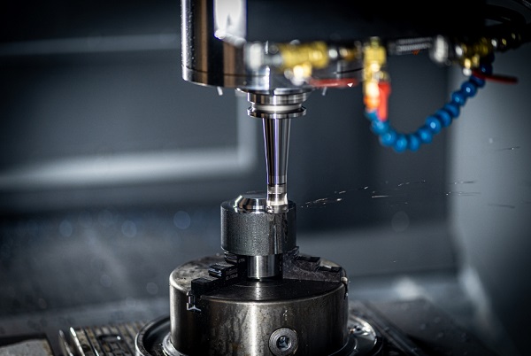
The Vibration Stiffness Loop
Your machine is just a rigid loop: Tool-Holder-Spindle-Table-Part. A bridgeport-style knee mill will never dampen vibration like a box-way vertical machining center with a mineral-cast base. For a typical aerospace aluminum bracket, we use a 40-taper spindle with a dual-contact face-and-taper holder. The data is clear: a standard CAT40 holder has a stiffness of roughly 20 N/µm, while a dual-contact system, by eliminating the gap between the flange and spindle nose, jumps past 35 N/µm. This single choice reduces the acceleration amplitude at the tool tip by half, directly protecting your surface finish specs.
Why Does Tool and Fixture Design Determine Precision?
You can own the most rigid machine on the market, but a poorly designed fixture or a run-of-the-mill tool holder will erase that investment instantly. This step is about controlling the interface.
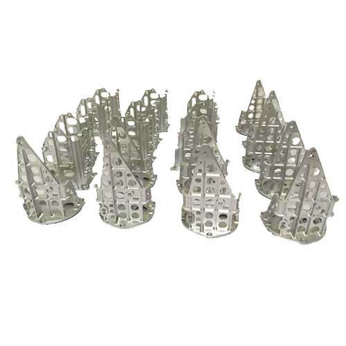
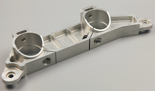
Clamping Force and Six-Point Location
The 3-2-1 principle is basic. For precision, we must discuss force-loop management. If you are clamping a thin-walled titanium part with a standard vise, you induce local plastic deformation. The moment you unclamp, the part springs back out of tolerance. The fix? We design custom piezo-electric soft jaws or use low-melting-point alloy encapsulators. For a jet engine blade root we produce, we transitioned from mechanical clamps to a hydrostatic fixture. The result was a reduction of clamping distortion from ±0.02 mm to under 0.005 mm, measurable on the CMM immediately after release.
Tool Runout Kills More Than Size
Here is a field truth: tool runout is the hidden scrap multiplier. If you measure a 3 µm runout at the tool tip, your 3-flute end mill is functionally a 1-flute end mill. One tooth is doing 95% of the work. This causes immediate chip packing and premature flank wear. We enforce a strict runout limit of 5 µm measured dynamically with a laser pre-setter. Shrink-fit and hydraulic holders are mandatory for any finishing pass under 3 mm. The extra cost of these holders is recovered within ten cycles just by saving the cost of scrapped high-nickel-alloy parts.
How to Calculate Cutting Parameters Scientifically?
“Feel” and “sound” are great mentors, but precision starts with physics. We don’t guess speeds and feeds; we negotiate them based on tool engagement and thermal limits.
Chip Thinning and Radial Engagement
Look at a chip thinning calculator. If you program a radial stepover (ae) of 10% of the cutter diameter, your actual chip thickness drops to roughly half the programmed feed per tooth. Running too light doesn’t polish; it rubs. Rubbing instantly work-hardens the surface of stainless steel and creates a white layer on the part surface that destroys fatigue life. We fix this by boosting the programmed feed rate to match the manufacturer’s recommended chip thickness. For a 10 mm end mill in 316 stainless, we run a cutting speed (Vc) of 180 m/min, a feed per tooth (fz) of 0.05 mm, but an axial depth (ap) of 12% of the diameter. This high-speed dynamic milling path keeps the tool in a consistent thermal load, enabling us to hold a ±0.01 mm width tolerance over a 500-part production run without a sizing pass.
The Thermal Budget of a Cut
Think of heat as a physical chip. Most of that heat should evacuate with the blue steel curl. If your chip is silver and the part is hot, you are rubbing. We use high-pressure coolant (70 bar) right at the tool tip, not just to cool, but to blast the recut-proof barrier away. In a recent job involving a deep hollow shaft, we switched from flood coolant to a through-tool system and saw the part temperature drop by 15°C, effectively eliminating the 0.008 mm of thermal growth that was ruining the afternoon shift parts.
| Parameter State | Common Error | Precision Fix | Expected Result |
|---|---|---|---|
| Runout Control | Visual check only | Laser dynamic measurement <5 µm | Tool life +20%, Surface finish Ra <0.4 |
| Radial Stepover | Fixed 50% stepover | Chip thinning comp + 10% ae trochoidal path | Vibration eliminated, Vc can increase 30% |
| Coolant Pressure | Low-pressure flood (10 bar) | Through-tool high pressure (70 bar) | Chip recutting stop, size stability secured |
| Zero Setting | Touch probe only | Probe + In-cycle laser measurement | Batch variance reduced to <0.005 mm |
What Are the Best Practices for Machining Execution?
Code is perfect, but the physical world is messy. Your execution strategy must bridge this gap with metrology-based corrections.
The In-Cycle Thermal Compensation
No shop is perfectly climate-controlled. Our CNC grinders are, but the VMCs aren’t. To master this, you must probe the part geometry in-cycle. Here is our standard lock-step: rough the feature, pause, probe the current dimension. The macro calculates the current deviation from the target. The finish pass then offsets the coordinate system by exactly this deviation. For a deep bore finishing cycle, we use an air gauge in the tool magazine. The machine automatically changes the tool to the air gauge, measures the bore tapering caused by the tool’s cutting tip wear, and adjusts the boring head offset before the final spring pass. This closed-loop logic is proven to keep a φ25 H7 bore within a 3 µm band all day long.
Swarf Management
The enemy of a fine finish is a chip stuck on a wiper insert. We program a “chip breaking dwell” and a high-pressure wash-down sequence before finish toolpaths. In deep milling pockets, we use a “woodpecker” retract cycle, not to break the chip, but to force the coolant flush. Your surface finish spec (Ra 0.4) is directly dependent on your swarf control. It is non-negotiable.
How Do You Verify with Online and Final Inspection?
Measuring a part while it’s hot is a recipe for doom. Your final inspection isn’t just checking the part; it’s checking your entire process stability.
Metrology Correlation and Shrink Rule
You must establish a thermal equilibrium time. If you just finished a part that is at 30°C, and your CMM room is 20°C, do not measure instantly. You will see a false out-of-tolerance condition. We place parts on a granite surface plate between two CMM cycles, using calibrated thermometers to confirm the part hit 20°C ±0.5°C. You need to know the coefficient of thermal expansion (CTE) for your material. For a 100 mm aluminum bore, a 5°C deviation creates a 0.012 mm error—massive in the IT6 world. Apply the math before you reject the part.
Surface Texture as a Fingerprint
Don’t just rely on Ra. Use Rz and Rsk values. A mirror finish with a negative Rsk (bearing a smooth profile) is perfect for a rotating shaft. A positive Rsk (spiky peaks) indicates aggressive cutting or built-up edge. We use profilometers that connect directly to our SPC software. If Rz starts trending up over 10 pieces, it is a predictive signal to change the tool, even if the nominal Ra is still passable. This is predictive quality, not just reactive.
Conclusion
Achieving Mastery in Precision Machining is a commitment to controlling variables. You started with a functionally interpreted blueprint and chose a stress-relieved material on a rigid, scaled machine. You quantified tool runout and clamped the part without distorting it. You calculated feed rates based on chip thinning physics and locked down your thermal growth with in-cycle probing. Finally, you validated results with temperature-controlled, correlated metrology. This step-by-step, closed-loop process is what turns a chaotic shop floor into a predictable, profitable precision powerhouse. The tolerance of IT6 is not a barrier; it’s a checklist. Follow it, and zero-defect manufacturing becomes your standard, not your accident.
FAQ
What is the most common beginners mistake in precision machining?
Ignoring thermal growth. They measure a cold part, compare it to a hot part, and chase the wrong offset, leading to long-term scrapping.
How do I choose the right cutting fluid for surface finish?
For ferrous materials, use a high-lubricity semi-synthetic with extreme pressure additives. It prevents the built-up edge formation that destroys Ra values.
Is it possible to achieve IT6 tolerance without a CMM?
Only with great risk. While a calibrated bore gauge and micrometer can measure size, a CMM is essential to validate geometric tolerances like circularity and parallelism.
Why does my vibration spike during the finishing pass?
You are likely taking an infeed depth (ap) smaller than the tool nose radius. This causes rubbing, not cutting. Increase the depth of cut or use a sharper wiper insert.
Get projects quote with Moshijia Technology
Struggling to close the gap between your prototype and full-scale production tolerances? At Moshijia Technology, we don’t just machine parts; we engineer process stability. Send us your challenging drawings, and our engineering team will provide a full Design for Precision Manufacturing (DFPM) feedback and a competitive quote within 24 hours. Let’s move from microns to volume.