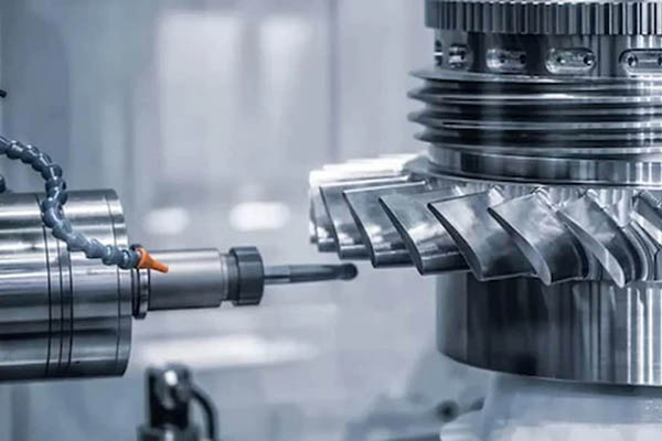
Master precision cnc machining with our ultimate shop guide covering CAD/CAM workflows, tooling parameter optimization, workholding setups, and micro-tolerance inspection protocols.
Introduction to Precision CNC Machining
Understanding Industrial Manufacturing Standards
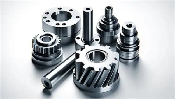
Modern industrial manufacturing demands parts with tight tolerances and complex geometries. Precision cnc machining serves as the backbone for high-tech sectors like aerospace, medical devices, and automotive engineering. This technique uses Computer Numerical Control (CNC) systems to automate subtractive manufacturing. Industrial standards require extreme accuracy, often holding dimensions within microscopic limits. Machinists must understand how raw blocks become aerospace-grade components. Every phase requires systematic verification to eliminate errors.
Addressing Micro-Level Target Tolerances
Achieving micron-level accuracy requires control over the entire machining environment. Standard machining handles general fractions, but precision manufacturing regularly manages tolerances down to ±0.005mm (±0.0002 inches). This level of precision leaves zero room for thermal expansion, machine deflection, or tool deflection. Programmers and machine operators must coordinate design files, raw material choices, and hardware rigidness. Ignoring a small parameter can cause immediate part rejection during quality control inspection.
Analyzing Typical Industry Applications
High-precision components operate in critical environments where part failure is dangerous. Medical bone screws require biocompatible materials and precise threads. Aerospace fuel nozzles demand complex internal channels and smooth surfaces. Semiconductor vacuum chambers require absolute flatness to maintain gas seals. These applications rely completely on precision cnc machining to meet mechanical performance standards. Using certified workflows helps machine shops deliver high-yield production runs consistently.
Step 1: CAD Design & 3D Modeling
Applying Design for Manufacturing Principles
Successful machining begins long before mounting a raw block onto a machine table. Engineers use Design for Manufacturing (DFM) rules to ensure parts are easy to machine. Complex visual designs mean nothing if a standard cutting tool cannot reach the internal cavities. Designers must avoid ultra-deep pockets, sharp internal corners, and extremely thin walls. Standard end mills are round, so they naturally leave radiused corners inside pockets. Adding proper corner radii allows smooth tool movement and minimizes machine cycle time.
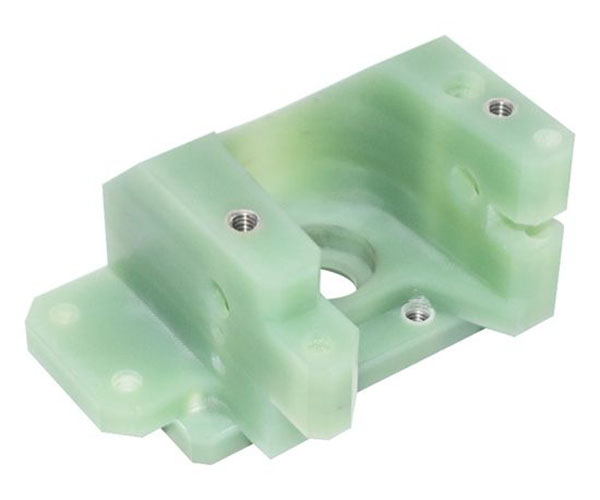
- Minimum Wall Thickness: Maintain at least 0.8mm for aluminum and 1.5mm for machined plastics to prevent warping.
- Pocket Depths: Keep the depth-to-diameter ratio below 4:1 to reduce tool deflection.
- Internal Radii: Ensure corner fillets match or exceed the radius of the roughing tool.
Implementing Geometric Dimensioning & Tolerancing
传统坐标标注容易在复杂装配体中造成公差累积。 Traditional coordinate dimensioning often creates tolerance accumulation across complex assemblies. Geometric Dimensioning & Tolerancing (GD&T) solves this problem by defining clear geometric relationships. GD&T utilizes feature control frames to specify exact flatness, parallelism, perpendicularity, and true position. Designers must establish reliable datum features based on how the part fits the final assembly. Correct datum selection gives machinists clear references for part setup and quality inspection processes.
Minimizing Stress Concentration Zones
Sharp internal edges concentrate mechanical stress and create weak points during cutting. These stress zones cause part deformation during machining and early failure during field use. Designers should use fillet radiuses that are 10% to 15% larger than the cutting tool radius. This design choice prevents the tool from engaging its full diameter in corners, reducing tool chatter. Gradual thickness transitions help distribute machining stress evenly throughout the raw metal stock.
Step 2: CAM Programming & Toolpath Generation
Selecting Optimal Strategic Toolpaths
Computer-Aided Manufacturing (CAM) software turns 3D models into exact tool movements. Programmers choose specialized strategies for roughing out material and finishing surfaces. Adaptive clearing paths maintain a constant tool engagement angle, allowing deep cuts without breaking tools. For finishing operations, parallel or constant-scallop toolpaths generate highly consistent surface finishes. Choosing the right toolpath strategy directly shortens total cycle times and reduces machine wear.
Optimizing Feed Rate Conversions
Translating CAM designs into actual machine movements requires precise feed rate control. Programmers must adjust cutting feeds when tools move through tight internal corners. Linear feed rates must slow down during circular interpolation to maintain the correct chip thickness. Modern CAM systems calculate step-overs and step-downs automatically based on the targeted surface roughness. Maintaining constant chip loads prevents material strain and extends overall cutting tool life.
Verifying Raw G-Code Output
Post-processors convert CAM data into standard G-code and M-code strings for the machine controller. Operators must check these raw code lines before starting a machining job. A misplaced decimal point or incorrect coordinate system call can cause serious machine crashes. Virtual simulation software tests toolpaths to catch collisions between the tool holder and workholding clamps. Manual code review confirms critical safety commands like G43 for tool length compensation and M08 for flood coolant activation.
Step 3: Machine Setup & Workholding
Maximizing Component Setup Rigidity
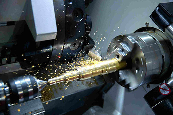
A precision machine tool needs a highly rigid foundation to achieve tight tolerances. Workholding fixtures must secure the workpiece against strong multi-directional cutting forces. Any vibration or movement during cutting creates dimensional errors and ruins the surface finish. Operators use heavy-duty modular vises, custom fixtures, and soft jaws to secure raw material blocks. Spreading clamping pressure evenly avoids distorting delicate, thin-walled parts.
Aligning Precise Workspace Coordinate Systems
Setting up the Work Coordinate System (WCS) links physical raw stock to digital program files. Machinists use precision edge finders, dial indicators, or automated optical probes to locate zero points. The G54 command establishes the primary origin point for the X, Y, and Z axes. Operators must verify alignment parallelism relative to the machine travel axes. A tiny setup misalignment causes angular errors across all machined features.
Controlling Workplace Thermal Expansion
Temperature changes alter the physical dimensions of machine components and raw workpieces. Large CNC machines generate significant internal heat from high-speed spindle motors and axis drives. A 5°C temperature increase can expand a steel machine bed by several microns. Precision machine shops use climate-controlled environments kept at exactly 20°C (68°F). Spindle chillers and thermal sensors help maintain stable machine geometry during long production runs.
Step 4: Tool Selection & Cutting Parameters
Matching Material Substrates Correctly
Choosing the correct tool substrate prevents premature wear and tool breakage. Solid carbide end mills offer excellent rigidity and heat resistance for cutting hard metals. High-Speed Steel (HSS) tools work well for softer aluminum alloys and plastics due to their flexibility. Cobalts and specialized ceramics handle tough titanium and nickel-based superalloys. Matching the tool material to the workpiece ensures clean cutting actions and prevents material smearing.
Calculating Precise Speeds and Feeds
Machinists calculate cutting speeds and feed rates using exact engineering formulas. Spindle Speed ($N$) depends on target Surface Feet per Minute ($SFM$) and tool diameter ($D$):
$$\text{N (RPM)} = \frac{\text{SFM} \times 3.82}{\text{D}}$$
Feed Rate ($F$) combines calculated RPM, number of cutting teeth ($z$), and recommended chip load per tooth ($f_z$):
$$\text{F (inch/min)} = \text{N} \times \text{z} \times f_z$$
Running outside these calculated parameters causes severe tool rubbing, excessive heat buildup, or immediate cutting-edge chipping.
Evaluating High Performance Tool Coatings
Advanced tool coatings add a hard protective barrier that extends cutting life. Titanium Aluminum Nitride (TiAlN) handles high-temperature dry machining in tough alloy steels. Diamond-Like Carbon (DLC) coatings prevent soft aluminum from sticking to cutting edges. These thin coatings reduce friction, assist chip evacuation, and protect tool sharp edges. Investing in coated tools lowers overall tooling costs by increasing production outputs between tool changes.
Step 5: Running the CNC Program
Execiting Initial Dry Runs Safely
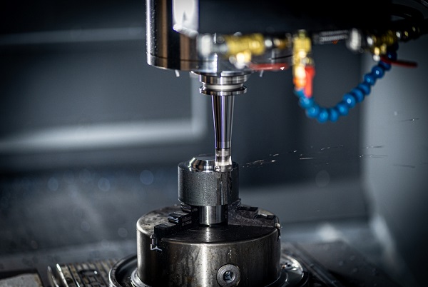
Never run a new G-code program directly into expensive raw material. Operators perform an initial dry run with the cutting tool positioned high above the workpiece. Running the program in mid-air lets the operator verify axis movements visually. Operators use the single-block execution mode to check the program line by line. Watching the distance-to-go display on the controller helps catch Z-axis programming errors before a crash occurs.
Monitoring Real-Time Cutting Indicators
Experienced operators use their senses to monitor machining conditions inside the enclosure. The sound of cutting should be a consistent hum rather than a high-pitched squeal. Spindle load meters show real-time force percentages during heavy cutting moves. Sudden spikes in spindle load indicate tool dulling or unexpected material hardness. Watching chip shapes helps confirm cutting performance; ideal chips are tightly curled and consistent in color.
Optimizing Lubrication and Coolant Delivery
Proper fluid delivery removes heat and flushes chips out of the cutting zone. Flood coolant keeps the workpiece at a stable temperature to prevent thermal expansion. High-pressure through-spindle coolant is necessary for deep hole drilling to prevent chip packing. For materials like eco-friendly plastics, Minimum Quantity Lubrication (MQL) applies fine oil mists directly to the tool edge. Proper lubrication stops chips from re-cutting, protecting the finished surface.
Step 6: Quality Inspection & Tolerance Verification
Calibrating Advanced Metrology Equipment
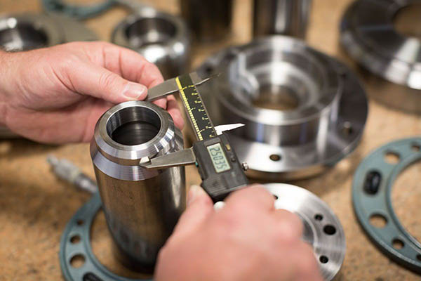
Quality verification is only as accurate as the inspection tools used. High-precision inspection requires digital micrometers, bore gauges, and gage block sets. Metrology tools must be calibrated regularly against traceable national standards. Even hand-held micrometers need regular zero-checking to remove measurement drift. Clean tools and parts prevent dust particles from altering micro-level dimension readings.
Operating Coordinate Measuring Machines
A Coordinate Measuring Machine (CMM) provides automated checking for complex, tight-tolerance geometries. These computer-controlled machines use sensitive touch probes or optical sensors to map part coordinates in 3D space. CMM software compares these physical measurements against original CAD models to check geometric tolerances. Operating inside temperature-controlled rooms ensures CMMs deliver accurate data for quality compliance reports.
Analyzing Finished Surface Roughness
Surface finish quality affects friction, wear characteristics, and cosmetic appearance. Surface profilometers measure micro-inch deviations across finished faces to calculate the Average Roughness ($R_a$). High-precision parts often require an $R_a$ value under 0.4 microns (16 micro-inches). Machinists adjust finish toolpath step-overs and insert radii to hit these smooth surface specs. Clean finishes eliminate micro-scratches that cause structural failure over time.
Advanced Techniques: Multi-Axis Machining & High-Speed Milling
Leveraging Simultaneous Multi Axis Systems
5-axis CNC machining centers move the cutting tool along five different axes simultaneously. This capability allows the tool to reach complex undercuts and compound angles in a single setup. Eliminating multiple fixtures reduces cumulative stack-up errors across different operations. 5-axis toolpaths can keep the cutter at an optimal contact angle, reducing tool wear and improving surface finishes. This approach streamlines production for complex aerospace impellers and medical implants.
Implementing High Speed Milling Rules
High-Speed Milling (HSM) combines high spindle speeds with light radial cuts and fast feed rates. This method keeps cutting heat inside the flying chips rather than transferring it into the part. HSM reduces cutting forces, making it ideal for thin-walled components prone to bending. Machinists use high-performance balanced tool holders to prevent spindle vibration at high speeds. This technique delivers high material removal rates along with excellent surface quality.
Troubleshooting Common Issues
Diagnosing Premature Cutting Tool Wear
A common shop issue is fast tool wear, which causes parts to drift out of tolerance. Abrasive wear happens when cutting hard materials at excessive surface speeds. Flank wear and built-up edge (BUE) occur when cutting speeds are too low for sticky metals like stainless steel. Operators should lower cutting speeds or change to a more heat-resistant tool coating to fix these wear issues. Regular tool wear tracking helps shops schedule tool changes before parts fail inspection.
Eliminating Harmonic Vibration and Chatter
Chatter is a loud harmonic vibration that leaves ugly ripple marks across machined surfaces. This vibration ruins surface finishes and breaks delicate carbide tools. Machinists stop chatter by changing spindle speeds slightly to alter vibration frequencies. Improving setup rigidity or shortening tool extensions also reduces tool deflection. Using variable-helix end mills breaks up harmonic patterns, resulting in quieter cutting and smoother finishes.
Correcting Dimensional and Surface Defects
When finished parts fail tolerance checks, operators must isolate the root cause systematically. Backlash in worn ball screws can cause round holes to turn slightly oval. Sub-surface burrs happen when dull tools tear through ductile metals instead of cutting cleanly. Operators should replace dull tools, verify fixture clamping force, and double-check thermal stability. Regular preventative maintenance keeps CNC machines running reliably within original factory specifications.
Best Practices & Future Trends
Enforcing Shop Preventive Maintenance
Consistent preventative maintenance schedules prevent unexpected machine downtime and costly scrap parts. Machine operators check way-lube levels and clean telescopic chip covers every day. Maintenance technicians check axis backlash and spindle drawbar pull force every month. Using laser interferometers to calibrate machine positioning ensures long-term positioning accuracy. Clean, well-lubricated machine tools hold tight tolerances for many years.
Integrating Artificial Intelligence and Automation
Artificial Intelligence (AI) is modernizing modern precision cnc machining workflows. Smart machine controllers use acoustic sensors to monitor tool wear automatically. If a drill breaks, the system pauses the cycle instantly to protect the workpiece. Robotic arm loaders load raw blocks into machines for continuous overnight production. AI software analyzes historical cutting data to optimize feed rates for future production runs.
Adopting Modern Digital Twin Concepts
Digital twin technology creates an exact virtual model of physical CNC machines and fixtures. Programmers run G-code programs on the digital twin to check axis limits and tool clearances safely. This advanced simulation catches programming errors without wasting machine time or raw materials. Connecting real-time machine sensors to digital twins helps managers monitor production efficiency from anywhere. Modern digital tools help machine shops maintain high productivity and low defect rates.
Frequently Asked Questions
What is the difference between standard and precision CNC machining?
Standard CNC machining typically achieves tolerances between ±0.1mm and ±0.05mm. Precision CNC machining holds much tighter tolerances, regularly reaching between ±0.005mm and ±0.001mm. Precision machining requires specialized climate control, highly rigid machine setups, high-grade tooling, and advanced metrology tools to control micro-level variations.
How do operators stop tool chatter during deep pocket milling?
Operators reduce tool chatter by shortening tool extensions to increase tool rigidity. Changing spindle speeds alters harmonic vibration frequencies to break up resonance. Using variable-helix or uneven flute spacing end mills also reduces harmonics. Finally, reducing the radial width of cut while maintaining axial depth helps stabilize the cutting action.
Why is thermal stability important in precision machine shops?
Materials expand when heated and contract when cooled. In precision manufacturing, a small temperature change can expand a raw block or machine spindle by several microns, pushing features out of spec. Keeping the shop floor at a stable 20°C (68°F) ensures parts match design dimensions from setup through final inspection.
Which tool coating works best for machining aluminum alloys?
Diamond-Like Carbon (DLC) and Titanium Diboride (TiB2) coatings work best for aluminum alloys. These coatings provide very low friction coefficients and high hardness. They prevent soft aluminum from sticking to the cutting edges, which eliminates built-up edge issues and improves surface finishes.
Get projects quote with Moshijia Technology
Ready to move your custom designs from CAD models into high-precision finished parts? Moshijia Technology provides professional precision cnc machining services with tight tolerances down to ±0.005mm. Our advanced multi-axis CNC machines, strict ISO 9001 quality controls, and expert engineering support ensure rapid prototyping and reliable production runs. Upload your STEP files today to get a fast industrial manufacturing quote.