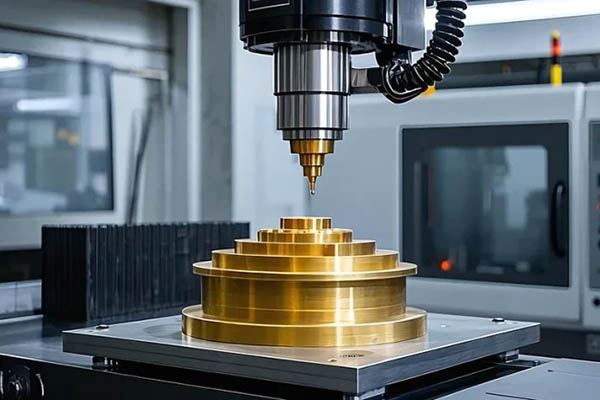
Master CNC machining bronze with our engineer-led guide. Learn optimal speeds, feeds, tool geometry, and chip control to eliminate work hardening and part deformation.
Bronze is a staple material in modern manufacturing. Industrial sectors rely on it for heavy-duty components. It delivers excellent thermal conductivity, corrosion resistance, and low friction. However, many machinists struggle when cnc machining bronze.
Bronze is often labeled as an easy-to-cut metal. This label creates a false sense of security. Certain alloys cause rapid tool wear. Others create long, gummy chips that wrap around spindles.
This guide breaks down the precise mechanics of cutting bronze. We share field-tested parameters, tooling strategies, and real-world fixes from our shop floor at Moshijia Technology.
1. Understanding Bronze Alloys for Machining
Not all bronze alloys behave the same way under a cutting tool. Choosing the wrong alloy or treating them identically leads to scrapped parts. We categorize these alloys into three main machining groups.
Free-Machining Bronze Alloys
C31600 Leaded Bronze and C54400 Phosphor Bronze represent this category. They contain lead or specialized additives. These elements act as internal lubricants.
The chips break easily during cutting. Tool wear remains very low. You can run high cutting speeds with minimal heat build-up. These alloys are ideal for high-volume electrical contacts and small bushings.
Moderately Machinable Bronze Alloys
C51000 Phosphor Bronze and C65500 Silicon Bronze fall into this middle tier. They lack heavy lead content but maintain decent stability.
Silicon bronze offers high strength and excellent corrosion resistance. However, it increases mechanical friction at the cutting zone. You must manage heat accumulation to prevent dimensional drift.
Difficult-to-Machine Bronze Alloys
C95400 Aluminum Bronze and C86300 Manganese Bronze are tough materials. They match the tensile strength of carbon steel.
Aluminum bronze forms a hard oxide layer during cutting. This layer causes abrasive wear on the tool flanks. These alloys also work-harden almost instantly. If your tool rubs instead of cutting, the surface glazes over. The next tool pass will then chip or break.
| Alloy Grade | Common Industrial Application | Machinability Rating (C36000 Brass = 100%) | Primary Machining Challenge |
| C31600 | Electrical connectors, fasteners | 80% | High burr formation on exits |
| C54400 | Sleeve bearings, thrust washers | 80% | Control of fine toxic dust |
| C51000 | Springs, sleeve bushings | 20% | Moderate work hardening |
| C65500 | Hydraulic valve stems, bolts | 30% | High friction, sticky chips |
| C95400 | High-load gears, marine hardware | 20% | Severe abrasive tool wear |
| C86300 | Actuator nuts, heavy-duty brackets | 8% | Extreme work hardening |
2. Tool Selection & Geometry Optimization
Standard carbide inserts meant for steel will fail on tough bronze. You need specific tool materials and sharp geometries.
Tool Material Selector
Uncoated micro-grain tungsten carbide is our default choice for non-leaded bronze. It maintains a very sharp edge. For high-volume runs of abrasive aluminum bronze, we switch to CVD diamond-coated carbide or PCD (Polycrystalline Diamond) tools. The diamond layer resists the abrasive nature of aluminum oxides. It extends tool life up to ten times.
Relief and Rake Angles
Bronze needs a clean shearing action. Avoid negative rake angles because they push the material and generate friction.
- Positive Rake Angle: Use a positive rake angle between $4^\circ$ and $8^\circ$. This splits the metal clean.
- Relief Angle: Use a generous relief angle between $10^\circ$ and $15^\circ$. This prevents the tool flank from rubbing against the newly cut bronze surface.
Edge Preparation Secrets
Never use heavily honed or blunted edges on tough bronze. The tool edge must stay sharp.
Keep your corner radius small. A large nose radius increases the contact area between the tool and the workpiece. This extra contact triggers tool deflection and chatter on thin walls. Use a maximum nose radius of 0.4 mm for roughing and 0.2 mm for finishing cuts.
3. Cutting Parameters: Speeds, Feeds & Depth of Cut
Balancing your cutting parameters prevents work hardening. The goal is to keep the cutting zone cool.
Speed and Feed Matrix
The table below outlines our baseline parameters for CNC turning and milling. These values assume you are using sharp carbide tooling.
| Operation Type | Alloy Group | Cutting Speed (Vc) | Feed Rate (f) | Depth of Cut (ap) |
| CNC Turning | Free-Machining (C31600) | 120–240 m/min | 0.15–0.40 mm/rev | 1.50–4.00 mm |
| CNC Turning | Tough Alloys (C95400) | 45–90 m/min | 0.10–0.25 mm/rev | 1.00–2.50 mm |
| CNC Milling | Free-Machining (C54400) | 150–300 m/min | 0.08–0.20 mm/tooth | 2.00–5.00 mm |
| CNC Milling | Tough Alloys (C86300) | 35–75 m/min | 0.05–0.12 mm/tooth | 0.80–2.00 mm |
Cold Machining Core Principles
To achieve a cold cut, you must follow two rules: high chip load and consistent engagement.
[Low Feed Rate]  --> Tool Rubs --> Friction Skyrockets --> Hardened Bronze Layer
[High Feed Rate] --> Clean Shear --> Heat Enters Chip   --> Cool Workpiece
Never let the tool dwell in the cut. If the feed stops while the spindle spins, the tool rubs. This creates a hard, glassy surface layer that destroys the next tool. Maintain a minimum chip load of 0.05 mm per tooth even during light finishing passes.

4. Step-by-Step Machining Process
Executing a bronze part requires strict control over every stage of the cycle.
Phase 1: Material Inspection
Check the hardness uniformity of your bronze bar stock or casting. Cast bronze often has a hard outer skin containing embedded sand or oxides.
Phase 2: Rough Machining
Remove the bulk of the material using a heavy depth of cut and stable feeds. Leave a uniform stock allowance of 0.5 mm to 0.8 mm for the finishing stages. If you leave too little material, the finishing tool will just rub against the work-hardened zone left by the roughing pass.
Phase 3: Semi-Finishing
This phase isolates the stress from roughing. Machine the part down to 0.15 mm within its final dimension. Measure the part here to check for thermal expansion.
Phase 4: Precision Finishing
Run at maximum spindle speeds and crisp feeds. Use a brand-new or dedicated finishing insert. Ensure the depth of cut is deeper than the work-hardened layer from the previous pass.
Phase 5: Quality Inspection
Allow the part to cool down completely to ambient room temperature ($20^\circ\text{C}$). Measure dimensions only after temperature stabilization. Check the surface roughness against your blueprint specs.
5. Chip Control & Coolant Management
Gummy bronze alloys produce long stringy chips. Abrasive bronze alloys create high heat. Both issues require targeted control strategies.
Chip Breaker Geometry
Use inserts featuring a narrow, aggressive chip breaker groove. For CNC milling, climb milling is mandatory.
Climb Milling: Tool enters thick part of chip first -> Snaps chip early -> Short chips
Conventional Milling: Tool enters thin part first  -> Rubs and drags       -> Long stringy chips
Climb milling forces the tool to cut from thick to thin. It creates a sudden impact that snaps brittle bronze chips easily.
Coolant Delivery Systems
Flood coolant is essential for cnc machining bronze. Use a water-soluble synthetic oil emulsion at a 10% to 12% concentration mix. This provides high lubrication to stop chips from welding to the tool edge.
For deep hole drilling or pocketing, use high-pressure through-spindle coolant. Aim for a minimum pressure of 20 bar. This force flushes out chips before they jam and snap your drill.
6. Deformation Prevention: Fixturing & Programming
Bronze has a relatively high coefficient of thermal expansion and moderate elasticity. It deforms easily under excessive clamping forces.
Advanced Jaw Designs
Standard hard steel serrated jaws crush and deform bronze tubes or thin-walled rings.
- Use pie-shaped soft aluminum jaws. They wrap completely around the circumference of the part. This spreads the clamping force evenly across $360^\circ$.
- Lower your hydraulic chuck pressure. Drop it to 8–12 bar to prevent out-of-round distortion.
Intelligent Toolpaths
Avoid high-impact slotting routines. Use trochoidal milling toolpaths instead.
Trochoidal paths keep the tool in a continuous, smooth circular motion. This step keeps the tool engagement angle low and uniform. It prevents sudden spikes in cutting forces, protecting thin walls from flexing or bending away from the cutter.
7. Inter-Process Treatments
Complex, tight-tolerance bronze parts accumulate internal stresses during heavy machining. These stresses must be relieved before final finishing.
Stress Relief Annealing
When milling large, asymmetric pockets, the material will warp as stress relieves itself. Stop machining after the roughing phase.
Place the semi-machined bronze parts into a heat-treatment furnace. Heat the oven to $260^\circ\text{C}$ to $315^\circ\text{C}$. Hold this temperature for one hour per inch of material thickness, then let it cool slowly in still air. This process resets the internal molecular matrix without altering overall material hardness.
Edge De-Burring Strategies
Bronze leaves stubborn, razor-sharp burrs on exits. प्रोग्राम complete chamfering routines directly into your CNC code. Use a $45^\circ$ carbide spotting drill or deburring tool to clear edges before the final finishing pass.
8. Surface Finishing Techniques
Many industrial applications require specific surface properties for wear resistance or aesthetics.
As-Machined Surfaces
With optimal parameters, a sharp carbide tool yields an as-machined surface roughness of $R_a\ 0.8\ \mu\text{m}$. Ensure your feed lines are uniform by keeping a constant feed-to-speed ratio.
Mechanical Post-Processing
- Manual Polishing: Uses ultra-fine diamond pastes on felt bobs to achieve a mirror finish ($R_a < 0.2\ \mu\text{m}$). This is ideal for rotary seal faces.
- Bead Blasting: Uses fine glass beads at 4 bar pressure to create a uniform matte look. It removes minor tooling tracks.
- Brushing: Uses abrasive nylon wheels to create a directional grain texture for architectural components.
9. Common Challenges & Solutions
Our production floor uses this quick troubleshooting matrix when problems surface during bronze runs.
[Problem: Rapid Flank Wear] ----> Check Speed ----> Drop speed 20%, switch to PCD
[Problem: Severe Part Burr]  ----> Check Edge  ----> Replace insert, increase exit clearance
[Problem: Surface Chatter]   ----> Check Setup ----> Reduce nose radius, improve clamping rigidity
Rapid Flank Wear
- Root Cause: Abrasive elements in aluminum or manganese bronze.
- Solution: Drop your cutting speed ($V_c$) by 20%. Switch to a harder micro-grain carbide or a diamond-coated tool.
Severe Part Burring
- Root Cause: The tool edge is blunt, or the feed rate is too low.
- Solution: Replace the worn insert with a polished, sharp-edged style. Increase the feed rate to ensure clean shearing.
Surface Chatter Marks
- Root Cause: Tool setup lacks rigidity, or the tool nose radius is too large.
- Solution: Shorten tool overhang. Reduce the insert nose radius down to 0.2 mm.
10. Case Study: High-Pressure Valve Manifold
A client tasked Moshijia Technology with manufacturing a high-pressure marine valve manifold. The material spec was solid C95400 Aluminum Bronze. The design featured a series of deep M20x2.5 internal threads.
The Problem
The initial attempt by a subcontractor failed. They experienced broken taps, torn internal thread flanks, and parts warping out of flatness by 0.12 mm.
The Moshijia Strategy
We re-engineered the process layout from scratch:
- Tooling Shift: We swapped the standard high-speed steel taps for a solid carbide thread mill with a specialized TiAlN coating.
- Toolpath Optimization: We programmed a helical climb-milling path to cut the threads. This method allowed us to control chip thickness precisely.
- Parameter Fine-Tuning: We set the cutting speed to 55 m/min and fixed the feed rate at 0.06 mm per tooth.
- Thermal Control: We delivered a 12% soluble oil mixture directly through the spindle at 30 bar pressure.
The Outcome
Thread milling eliminated tap breakage completely. The high-pressure coolant flushed chips out cleanly from the deep holes.
We added a mid-process stress relief bake to hold the flat manifold face within a strict 0.02 mm flatness tolerance. Total production cycle times dropped by 35%, and scrap rates hit zero.
FAQ
How do I prevent work hardening when cnc machining bronze?
Maintain a sharp tool edge and avoid low feed rates. Keep your chip load high enough to cut cleanly underneath the work-hardened layer left by the previous pass. Never let the tool dwell or rub against the metal surface.
Is coolant necessary for all bronze alloys?
Yes, flood coolant is highly recommended. While free-machining leaded bronze can technically be cut dry, using a rich water-soluble oil mix extends tool life and flushes away fine chips. Tougher alloys require high-pressure coolant to manage heat.
Why are my tools wearing out so fast on aluminum bronze?
Aluminum bronze contains hard aluminum oxide inclusions. These microscopic particles act like sandpaper on tool edges. You must use high-wear-resistance carbide grades or specialized diamond coatings to withstand this abrasive action.
Can I use standard steel-cutting inserts for bronze?
Avoid standard steel inserts. They often feature negative rake angles and heavy hones designed to strengthen the edge for steel chips. These geometries rub bronze, causing heat, work hardening, and part distortion. Use sharp, positive-rake inserts instead.
Get Projects Quote with Moshijia Technology
Need precision bronze components without the manufacturing headache? Moshijia Technology delivers high-tolerance CNC machined bronze parts for demanding industries worldwide. Send your CAD files to our engineering team today for a fast, competitive quote.