CNC plastic parts are integral components in countless industries, from automotive and electronics to medical devices and consumer goods. Their precision, consistency, and adaptability make them a top choice for applications requiring reliable performance. Whether you’re a seasoned manufacturer refining your machining processes, a designer optimizing part geometry for production, or a buyer seeking to understand the nuances of CNC plastic machining, this guide covers everything you need to know—from basic definitions to advanced design and cost-saving strategies. We’ll break down complex concepts with real-world examples, structured comparisons, and actionable steps to help you master the art and science of CNC plastic part production.
Introduction
The demand for high-precision CNC plastic parts continues to grow across industries, driven by advancements in plastic materials, CNC machining technology, and the need for lightweight, cost-effective components. Unlike traditional machining methods, CNC (Computer Numerical Control) machining offers unparalleled accuracy, repeatability, and flexibility, making it ideal for producing complex plastic parts in both low and high volumes. This guide is designed to address the core questions and challenges faced by professionals working with CNC plastic parts—from material selection and process initiation to tooling, fixturing, tolerances, cost control, and design optimization. By the end, you’ll have a comprehensive understanding of how to produce high-quality CNC plastic parts efficiently and cost-effectively.
What is a CNC plastic part?
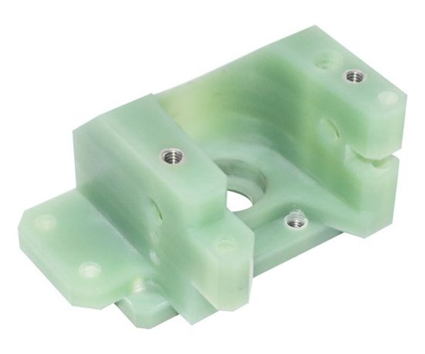
A CNC plastic part is a component manufactured by removing material from a plastic blank (or stock) using computer-controlled cutting tools. Unlike additive manufacturing processes (e.g., 3D printing), CNC machining is a subtractive process—material is precisely carved away to achieve the desired shape, dimensions, and surface finish.
Key characteristics of CNC plastic parts include:
- High precision and repeatability: CNC machines follow digital designs (CAD files) with tolerances as tight as ±0.001 inches, ensuring consistent part quality across production runs.
- Versatility: Capable of producing complex geometries, including internal features, threads, and contours that are difficult or impossible to achieve with other methods.
- Diverse material compatibility: Works with a wide range of plastic materials, from commodity plastics like ABS to high-performance engineered plastics such as PEEK.
Real-World Example: In the automotive industry, a leading manufacturer uses CNC-machined ABS plastic parts for interior trim panels. The precision of CNC machining ensures that the panels fit seamlessly with adjacent components, reducing assembly time and improving overall product quality. Over 10,000 units are produced annually with a defect rate of less than 0.5%, demonstrating the reliability of CNC plastic part production.
Which plastics suit CNC machining best?
Not all plastics are equally suited for CNC machining. The best candidates offer a balance of machinability (ease of cutting), dimensional stability, and mechanical properties. Below is a structured comparison of the most commonly used plastics for CNC plastic part production, along with their key attributes, applications, and machining considerations:
| Plastic Material | Machinability Rating (1-10, 10=Best) | Key Properties | Common Applications | Machining Considerations |
|---|---|---|---|---|
| Acetal (POM) | 9 | High rigidity, low friction, excellent dimensional stability, chemical resistance | Gears, bearings, bushings, automotive components | Produces fine chips; use sharp tools to avoid melting; low cutting forces required |
| ABS | 8 | Good impact resistance, rigidity, and surface finish; cost-effective | Consumer electronics casings, automotive interior parts, toys | Tends to form stringy chips; use chip breakers; moderate cutting speeds |
| Nylon (PA) | 7 | High tensile strength, abrasion resistance, good fatigue performance | Fasteners, fittings, gears, industrial components | Absorbs moisture (pre-dry before machining); use coolant to prevent melting |
| PEEK | 6 | High-temperature resistance, excellent chemical resistance, biocompatible | Medical devices, aerospace components, oil & gas parts | High cutting temperatures (use high-speed steel or carbide tools); dry machining recommended |
| PVC | 5 | Low cost, good chemical resistance, flame retardant | Pipes, fittings, industrial enclosures | Emits toxic fumes when heated (ensure proper ventilation); use sharp tools |
| PTFE (Teflon) | 4 | Extremely low friction, excellent chemical resistance, high-temperature resistance | Gaskets, seals, non-stick components | Soft and gummy; use slow cutting speeds and high feeds; secure fixturing critical |
Key Fact: According to industry data, Acetal and ABS account for over 40% of all CNC plastic part production due to their superior machinability and cost-effectiveness. High-performance plastics like PEEK, while more difficult to machine, are growing in demand at a CAGR of 6.2% (2023-2028) due to their use in high-tech industries.
How does the CNC process start for plastics?
The process of manufacturing a CNC plastic part follows a structured, sequential workflow that ensures precision and efficiency. Below is a step-by-step breakdown of the initiation process, with actionable details for each stage:
- Design & CAD File PreparationThe first step is to create a detailed 3D CAD (Computer-Aided Design) model of the part. The design should include all critical dimensions, tolerances, surface finish requirements, and features (e.g., holes, threads, contours). For CNC machining, it’s essential to optimize the design for subtractive manufacturing—avoiding undercuts, ensuring sufficient material thickness for fixturing, and minimizing complex features that increase machining time. Pro Tip: Use CAD software with CNC machining simulation tools (e.g., Fusion 360, SolidWorks CAM) to identify potential issues (e.g., tool collisions, insufficient material) before machining begins.
- Material Selection & Blank PreparationBased on the part’s application and design requirements, select the appropriate plastic material (refer to the previous section). The plastic blank should be larger than the final part dimensions to account for material removal. For materials that absorb moisture (e.g., Nylon, PC), pre-dry the blank in an oven (typically 120-180°F for 2-4 hours) to prevent dimensional inaccuracies and poor surface finish.
- CAD to CAM ConversionConvert the CAD file to a CAM (Computer-Aided Manufacturing) program. The CAM software generates G-code (the programming language that controls CNC machines) by defining toolpaths, cutting speeds, feeds, and tool selection. For plastic machining, key parameters to set include:
- Cutting speed: Typically 500-3000 SFM (surface feet per minute), depending on the material.
- Feed rate: 0.001-0.010 IPR (inches per revolution), to avoid melting and ensure clean cuts.
- Depth of cut: 0.010-0.100 inches per pass, to reduce cutting forces and prevent part deformation.
- Machine Setup & Tool LoadingLoad the G-code into the CNC machine and mount the appropriate cutting tools (e.g., end mills, drills, reamers). For plastic machining, carbide tools are preferred over high-speed steel (HSS) because they maintain sharp edges longer and dissipate heat more effectively. Ensure the tools are properly aligned and secured to avoid vibration.
- Fixturing the Plastic BlankSecure the plastic blank to the machine’s worktable using appropriate fixturing (e.g., vises, clamps, vacuum chucks). The fixturing should be tight enough to prevent movement during machining but not so tight that it deforms the blank (critical for thin or brittle plastics). Use soft jaws or rubber pads to protect the plastic surface from damage.
- Test Run & CalibrationPerform a dry run (without cutting material) to verify the toolpaths and ensure no collisions occur. Then, conduct a test cut on a scrap piece of the same plastic material to check dimensions, surface finish, and tool performance. Adjust the G-code parameters as needed before initiating full production.
Case Study: A medical device manufacturer producing CNC plastic parts (PEEK surgical instruments) streamlined their process by integrating CAD/CAM simulation. This reduced setup time by 30% and eliminated tool collisions, which had previously caused 15% of production delays. The test run step also ensured that each part met the strict dimensional tolerances required for medical applications.
What tooling tricks prevent plastic melting?
Plastic materials have lower melting points than metals, making melting a common challenge during CNC machining. Melting can ruin surface finish, cause dimensional inaccuracies, and clog cutting tools. Below are proven tooling tricks and strategies to prevent melting in CNC plastic part production:
1. Choose the Right Tool Material & Geometry
- Carbide tools: As mentioned earlier, carbide tools are ideal for plastic machining because they have high thermal conductivity and maintain sharp edges. Dull tools generate more heat, so replacing or sharpening tools regularly is critical.
- Sharp cutting edges: Use tools with a high rake angle (15-30°) and sharp cutting edges to minimize material deformation and heat generation. Avoid tools with rounded edges, which crush rather than cut plastic.
- Multiple flutes: For most plastics, 2-4 flute end mills are recommended. More flutes increase contact area and heat generation, while fewer flutes allow for better chip evacuation (critical for preventing clogging and melting).
2. Optimize Cutting Parameters
- High cutting speeds, low feeds: Increasing cutting speed reduces the time the tool is in contact with the plastic, minimizing heat transfer. However, feeds should be low enough to ensure clean cuts—too high a feed rate can increase cutting forces and heat.
- Shallow depth of cut: Making multiple shallow passes (instead of one deep pass) distributes heat more evenly and reduces the amount of heat generated per pass. This is especially effective for heat-sensitive plastics like PVC and PTFE.
3. Use Coolant or Air Blast
- Compressed air: For most plastics, a compressed air blast is sufficient to cool the tool and workpiece, and blow away chips. This avoids the need for liquid coolants, which can be difficult to clean off plastic parts and may cause swelling in moisture-sensitive materials.
- Liquid coolants (when necessary): For high-performance plastics (e.g., PEEK) or high-volume production, use a water-soluble coolant with a low concentration (5-10%). Ensure the coolant is directed directly at the cutting zone to maximize heat dissipation.
4. Improve Chip Evacuation
- Toolpath optimization: Use climb milling (instead of conventional milling) for plastics. Climb milling produces smaller, easier-to-evacuate chips and reduces tool wear and heat generation.
- Chip breakers: For plastics that tend to form stringy chips (e.g., ABS, Nylon), use tools with built-in chip breakers to break chips into small pieces that can be easily blown away.
Key Statistic: According to a survey of CNC machinists, using sharp carbide tools with optimized cutting parameters reduces plastic melting incidents by 75%. Poor chip evacuation is the second leading cause of melting, accounting for 20% of defects in CNC plastic part production.
How do you hold thin or brittle plastic blanks?
Thin (≤0.100 inches) or brittle (e.g., acrylic, polystyrene) plastic blanks are prone to deformation, cracking, or chipping during CNC machining if not properly held. The goal of fixturing is to distribute clamping force evenly, minimize contact pressure, and prevent movement. Below are effective fixturing methods and tips for holding thin or brittle plastic blanks:
1. Vacuum Fixturing
Vacuum chucks are ideal for thin plastic blanks because they distribute clamping force evenly across the entire surface, eliminating localized pressure points that cause deformation. They also minimize contact with the blank, reducing the risk of surface damage.
Application Tips: Use a vacuum chuck with a porous surface (e.g., aluminum with tiny holes) to ensure uniform vacuum pressure.For very thin blanks (≤0.050 inches), use a backing plate (e.g., rigid foam, aluminum) to provide additional support and prevent warping.Ensure the blank is flat and clean before applying vacuum—debris or uneven surfaces can reduce vacuum effectiveness.
2. Soft Jaw Vises
Vises with soft jaws (made of aluminum, brass, or rubber) are suitable for brittle plastics that are prone to chipping. The soft jaws distribute clamping force and protect the plastic surface from scratches or indentations.
Application Tips: Machine the soft jaws to match the contour of the blank for a custom fit, which further distributes clamping force.Use minimum clamping force necessary to hold the blank—test the force by gently tapping the blank to ensure it doesn’t move.
3. Double-Sided Tape
For extremely thin or small plastic blanks, double-sided tape (e.g., high-strength acrylic tape) can be used to secure the blank to a rigid backing plate. This method is simple, cost-effective, and minimizes deformation.
Application Tips: Use tape with a high bond strength but low residue to avoid damaging the plastic surface when removing the part.Apply even pressure to the blank after attaching it to the tape to ensure full contact.Use a backing plate (e.g., aluminum) to provide rigidity and transfer cutting forces to the machine table.
4. Mechanical Clamps with Pressure Pads
For larger thin blanks, use mechanical clamps with rubber or foam pressure pads. The pads distribute clamping force and prevent indentations. Position the clamps as close to the cutting area as possible to minimize vibration and deflection.
Real-World Example: A manufacturer of acrylic display cases (thin CNC plastic parts) switched from standard vises to vacuum fixturing. This reduced deformation rates from 25% to 3% and improved surface finish quality. The vacuum chuck also allowed for faster setup times, increasing production efficiency by 18%.
Which tolerances are realistic in plastic CNC work?
Tolerance capabilities in CNC plastic part machining depend on several factors, including the plastic material, part size, geometry, machining process, and fixturing. While CNC machines are capable of very tight tolerances, plastic’s inherent properties (e.g., thermal expansion, moisture absorption, low rigidity) limit what is realistic. Below is a detailed breakdown of realistic tolerances for common plastic materials and part sizes:
| Plastic Material | Part Size (Inches) | Realistic Tolerance (± Inches) | Notes |
|---|---|---|---|
| Acetal (POM) | ≤2 | 0.001-0.003 | Excellent dimensional stability; tightest tolerances among common plastics |
| Acetal (POM) | 2-6 | 0.003-0.005 | Minor thermal expansion at larger sizes |
| ABS | ≤2 | 0.002-0.004 | Good stability; suitable for most consumer and industrial applications |
| ABS | 2-6 | 0.004-0.006 | Slight warping possible with uneven material removal |
| Nylon (PA) | ≤2 | 0.003-0.005 | Moisture absorption affects tolerance; pre-dry before machining |
| Nylon (PA) | 2-6 | 0.005-0.008 | Higher thermal expansion than Acetal or ABS |
| PEEK | ≤2 | 0.002-0.004 | High-temperature stability; tight tolerances possible with proper cooling |
| PEEK | 2-6 | 0.004-0.007 | Requires specialized tooling to maintain tolerances |
| Acrylic (PMMA) | ≤2 | 0.002-0.004 | Brittle; tight tolerances require gentle machining |
| Acrylic (PMMA) | 2-6 | 0.004-0.006 | Prone to cracking if tolerances are too tight |
Factors Affecting Tolerance Accuracy
- Thermal expansion: Plastics expand and contract with temperature changes. Machining in a temperature-controlled environment (68-72°F) can reduce tolerance variations by up to 50%.
- Moisture absorption: Materials like Nylon and PC absorb moisture, causing dimensional changes. Pre-drying and machining in a dry environment are critical for maintaining tolerances.
- Part geometry: Complex geometries (e.g., thin walls, deep pockets) are more prone to deflection during machining, increasing tolerance variations. Designing parts with uniform wall thickness can improve tolerance accuracy.
- Fixturing: Inadequate fixturing causes part movement, leading to tolerance errors. Using the right fixturing (e.g., vacuum chucks for thin parts) is essential.
Industry Best Practice: For critical CNC plastic parts requiring tight tolerances (±0.001 inches), use Acetal or PEEK, machine in a temperature-controlled environment, and perform post-machining inspection using coordinate measuring machines (CMMs) to verify dimensions.
What are the hidden cost drivers in plastic machining?
When producing CNC plastic parts, many costs are obvious (e.g., material, labor, machine time), but hidden cost drivers can significantly increase the total production cost. Identifying and addressing these hidden costs is critical for improving profitability. Below are the most common hidden cost drivers and strategies to mitigate them:
1. Tool Wear and Replacement
Plastic machining can cause rapid tool wear, especially when machining abrasive plastics (e.g., filled Nylon) or high-temperature plastics (e.g., PEEK). Dull tools reduce machining efficiency, increase scrap rates, and require frequent replacement—all of which add hidden costs.
Mitigation Strategies: Use high-quality carbide tools instead of HSS tools—they last 3-5 times longer, reducing replacement costs.Implement a tool maintenance schedule (e.g., sharpening tools after a set number of parts) to extend tool life.Optimize cutting parameters to reduce tool wear (e.g., avoid excessive cutting speeds for abrasive materials).
2. Scrap and Rework
Scrap and rework are major hidden costs in CNC plastic part production. Common causes include melting, deformation, tolerance errors, and surface finish defects. Scrap rates of 5-15% are common in unoptimized processes, leading to wasted material and labor.
Mitigation Strategies: Perform test cuts and dry runs to identify issues before full production.Use quality control (QC) checks at key stages (e.g., after roughing, before finishing) to catch defects early.Optimize fixturing and tooling to reduce deformation and melting (refer to previous sections).
3. Setup Time
Long setup times (e.g., tool loading, fixturing, G-code programming) increase labor costs and reduce machine utilization. For low-volume production, setup time can account for up to 40% of the total production cost.
Mitigation Strategies: Use CAD/CAM software with template libraries to automate G-code programming.Invest in quick-change tooling and fixturing systems (e.g., modular vises, tool holders) to reduce setup time by 30-50%.Standardize setup processes and train operators to improve efficiency.
4. Post-Machining Processing
Many CNC plastic parts require post-machining processing (e.g., deburring, cleaning, assembly, surface finishing), which adds hidden labor and material costs. These processes are often overlooked during cost estimation.
Mitigation Strategies: Design parts to minimize post-machining needs (e.g., avoid sharp edges that require deburring).Integrate post-machining steps into the CNC process (e.g., using a chamfer tool to eliminate deburring).Use automated post-machining equipment (e.g., robotic deburring) to reduce labor costs.
5. Material Waste
Material waste from inefficient nesting (arranging parts on the blank to minimize scrap) and over-sizing blanks adds hidden costs. For expensive plastics (e.g., PEEK), material waste can account for 20-30% of the material cost.
Mitigation Strategies: Use nesting software to optimize part placement on the blank, reducing scrap by 15-25%.Minimize blank over-size (e.g., use blanks that are only 0.100-0.200 inches larger than the final part).Recycle scrap material (where possible) to offset material costs.
Case Study: A manufacturer of CNC plastic parts for the electronics industry identified tool wear and scrap as their top hidden cost drivers. By switching to carbide tools and implementing a QC check system, they reduced tool replacement costs by 40% and scrap rates from 12% to 3%. This resulted in a 15% reduction in total production costs.
How do you design parts to minimize machining time?
Machining time is a major cost driver for CNC plastic part production. Optimizing part design to minimize machining time can significantly reduce costs, improve efficiency, and increase production capacity. Below are key design strategies to minimize machining time, organized by design element:
1. Simplify Geometry
- Avoid complex features: Features like deep pockets, undercuts, and narrow channels require multiple toolpaths and specialized tools, increasing machining time. Use simple, straight-line features where possible.
- Eliminate unnecessary features: Remove non-critical features (e.g., decorative grooves, unnecessary holes) that add machining time without improving part performance.
- Use standard geometries: Standard shapes (e.g., circles, squares) are faster to machine than custom shapes. Use standard thread sizes and hole diameters to avoid specialized tooling.
2. Optimize Part Dimensions
- Uniform wall thickness: Parts with uniform wall thickness require fewer tool passes and reduce the risk of deformation, which can add rework time. Aim for wall thickness variations of no more than 20%.
- Minimize depth-to-width ratios: Deep pockets or holes (depth-to-width ratio >4:1) require long tools and multiple passes, increasing machining time. Keep depth-to-width ratios ≤3:1 where possible.
- Avoid tight tolerances where not needed: Tight tolerances require slower cutting speeds and more passes. Specify tight tolerances only for critical features (e.g., mating surfaces), and use looser tolerances for non-critical features.
3. Design for Machining Efficiency
- Use accessible features: Ensure all features are accessible from the top or side of the part to avoid re-fixturing (which adds setup and machining time). Avoid features that require the part to be flipped or rotated multiple times.
- Incorporate chamfers or fillets: Chamfers (beveled edges) and fillets (rounded edges) can be machined quickly with a single tool pass and eliminate the need for post-machining deburring.
- Group similar features: Group features that require the same tool (e.g., all holes of the same size) to minimize tool changes, which add time. Tool changes can take 30-60 seconds each, so reducing them significantly improves efficiency.
4. Leverage Machining Best Practices in Design
- Allow for tool clearance: Ensure there is sufficient space around features for the cutting tool to move freely. Lack of tool clearance requires additional toolpaths and slower speeds.
- Use lead-in and lead-out paths: Design parts to allow for smooth lead-in (entry) and lead-out (exit) toolpaths, which reduce tool wear and machining time. Avoid abrupt tool changes that cause vibration.
Example: A designer optimized a CNC plastic part for a consumer electronics device by simplifying the geometry (removing non-critical decorative features), using uniform wall thickness, and grouping all holes of the same size. This reduced machining time from 8 minutes per part to 4.5 minutes per part—a 44% reduction. The optimized design also improved part consistency, reducing scrap rates by 5%.
When should you pick CNC over 3D printing for plastics?
Choosing between CNC machining and 3D printing for plastic parts depends on several factors, including part requirements, production volume, cost, and lead time. While 3D printing is ideal for prototyping and complex geometries, CNC machining offers advantages in precision, surface finish, and production efficiency for many applications. Below is a detailed comparison and guidance on when to choose CNC over 3D printing for CNC plastic parts:
| Factor | CNC Machining | 3D Printing | When to Choose CNC |
|---|---|---|---|
| Precision & Tolerances | Tight tolerances (±0.001-0.008 inches); high repeatability | Looser tolerances (±0.005-0.030 inches); lower repeatability | When parts require tight tolerances (e.g., mating components, medical devices) |
| Surface Finish | Smooth surface finish (Ra 10-60 microinches); no layer lines | Layered surface finish (Ra 50-200 microinches); requires post-processing for smoothness | When parts need a high-quality surface finish without post-processing (e.g., consumer products, display parts) |
| Production Volume | Efficient for low to high volumes (10-10,000+ parts) | Efficient for low volumes (1-10 parts); slow for high volumes | When production volume exceeds 10 parts; CNC setup costs are amortized over higher volumes |
| Material Selection | Wide range of engineering plastics (e.g., PEEK, Acetal, Nylon) with consistent properties | Limited to 3D printing-specific materials (e.g., PLA, PETG); some engineering plastics available but expensive | When parts require high-performance plastics (e.g., high-temperature, chemical-resistant) with consistent mechanical properties |
| Lead Time (High Volume) | Fast for high volumes; setup time is offset by quick machining cycles | Slow for high volumes; each part is printed individually | When high-volume production requires fast lead times (e.g., mass-produced consumer goods) |
| Mechanical Properties | Isotropic properties (uniform strength in all directions); same as bulk plastic | Anisotropic properties (weaker in layer direction); lower strength than bulk plastic | When parts require high strength and uniform mechanical properties (e.g., structural components, gears) |
Key Scenarios to Choose CNC Machining
- Production of precision components: Parts that require tight tolerances and consistent dimensions (e.g., automotive sensors, medical instruments, electronic connectors).
- High-volume production: When producing 10+ parts, CNC machining is more cost-effective and efficient than 3D printing.
- High-performance material requirements: Parts that need engineering plastics (e.g., PEEK, Acetal) with superior mechanical, thermal, or chemical properties.
- High surface finish requirements: Parts that need a smooth, uniform surface finish without post-processing (e.g., consumer electronics casings, display parts).
- Structural components: Parts that require isotropic strength and durability (e.g., gears, bearings, brackets).
Industry Insight: According to a 2024 survey of manufacturers, 78% of companies choose CNC machining over 3D printing for high-volume CNC plastic part production due to lower per-unit costs and higher quality. For prototyping, however, 65% use 3D printing for its faster setup time.
Conclusion
Producing high-quality CNC plastic parts requires a comprehensive understanding of material selection, process optimization, tooling, fixturing, tolerances, cost control, and design. By following the guidance in this guide, you can overcome common challenges (e.g., plastic melting, part deformation, hidden costs) and produce CNC plastic parts efficiently and cost-effectively.
Key takeaways include: choosing the right plastic material for machinability and application; optimizing tooling and cutting parameters to prevent melting; using appropriate fixturing for thin or brittle parts; specifying realistic tolerances based on material and part size; identifying and mitigating hidden cost drivers; optimizing part design to minimize machining time; and choosing CNC over 3D printing for precision, high-volume, or high-performance applications.
Whether you’re a manufacturer, designer, or buyer, mastering these concepts will help you make informed decisions and achieve better results in CNC plastic part production.
FAQ About CNC Plastic Part
Q1: What is the most machinable plastic for CNC plastic part production?
Acetal (POM) is widely considered the most machinable plastic for CNC plastic part production, with a machinability rating of 9/10. It offers excellent dimensional stability, produces fine chips, and requires low cutting forces, making it easy to machine with minimal defects.
Q2: Can CNC plastic parts achieve the same tolerances as metal CNC parts?
No, CNC plastic parts typically cannot achieve the same tight tolerances as metal parts due to plastic’s inherent properties (e.g., thermal expansion, moisture absorption, low rigidity). While metal parts can achieve tolerances as tight as ±0.0005 inches, the tightest realistic tolerances for plastic parts are ±0.001 inches (for Acetal or PEEK).
Q3: How can I reduce the cost of CNC plastic part production?
To reduce costs, focus on minimizing machining time (optimize part design), reducing scrap rates (improve tooling and fixturing), extending tool life (use carbide tools), optimizing material usage (nesting software), and reducing setup time (quick-change tooling and CAD/CAM templates).
Q4: Is coolant necessary for CNC plastic part machining?
Coolant is not always necessary. For most plastics, a compressed air blast is sufficient to cool the tool and workpiece and blow away chips. Liquid coolant is only recommended for high-performance plastics (e.g., PEEK) or high-volume production where heat buildup is a major concern.
Q5: When is 3D printing a better choice than CNC for plastic parts?
3D printing is better for low-volume prototyping (1-10 parts), complex geometries with undercuts or internal cavities that are difficult to machine, and when fast setup time is critical. It is not ideal for high-volume production, tight tolerances, or high-performance material requirements.
Get parts manufacturing quote with Moshijia
At Moshijia Technology, we specialize in high-precision CNC plastic part manufacturing for a wide range of industries, including automotive, electronics, medical, and consumer goods. With over 15 years of experience in CNC machining, we bring deep expertise in material selection, process optimization, and cost control to every project.
Our team of skilled engineers and machinists uses state-of-the-art CNC equipment, high-quality carbide tooling, and temperature-controlled environments to ensure that every CNC plastic part meets your exact specifications—from tight tolerances to superior surface finish. We work with all major plastic materials, including Acetal, ABS, Nylon, PEEK, and acrylic, and offer customized solutions to meet your unique application needs.
We understand that cost and lead time are critical for your success. That’s why we optimize every step of the production process—from design consultation to post-machining processing—to minimize costs and deliver parts on time. Our commitment to quality is reflected in our ISO 9001 certification and our rigorous QC processes, which ensure that every part meets the highest standards.
Whether you need low-volume prototypes or high-volume production runs, Moshijia Technology is your trusted partner for CNC plastic part manufacturing. Contact us today to get a free, no-obligation quote for your project.