Anodized CNC machining parts are widely used in aerospace, automotive, electronics, and consumer goods industries due to their superior corrosion resistance, enhanced aesthetics, and improved surface hardness. For manufacturers and engineers, mastering the key aspects of anodizing for CNC-machined components—from material selection to process optimization and quality control—directly impacts product performance and market competitiveness. This guide covers all critical topics to help you navigate the complexities of producing high-quality anodized CNC machining parts, addressing common challenges and providing actionable solutions based on industry experience and verified data.
Introduction
The combination of CNC machining and anodizing has become a cornerstone in modern manufacturing, enabling the production of precision components with exceptional surface properties. Anodized CNC machining parts offer a unique blend of dimensional accuracy and surface durability, making them indispensable in applications where both form and function are critical. Whether you’re manufacturing aluminum enclosures for electronics or structural components for aerospace, understanding how to optimize the CNC machining and anodizing process chain is essential to avoid defects, maintain tight tolerances, and ensure consistent quality. This guide is designed for senior manufacturing engineers, process managers, and product developers who seek to deepen their expertise in producing reliable anodized CNC components.
What is anodized CNC machining?
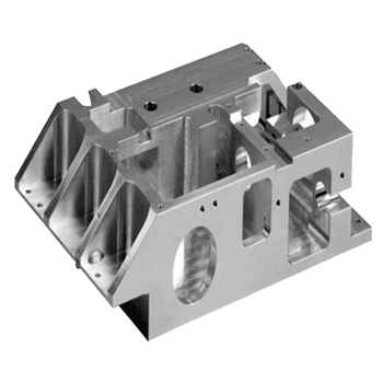
Anodized CNC machining refers to the process of first using Computer Numerical Control (CNC) equipment to precision-machine metal workpieces (primarily aluminum alloys) into the desired shape, followed by anodization—a electrolytic passivation process that forms a protective oxide layer on the metal’s surface. This two-step process combines the high precision of CNC machining (which ensures dimensional accuracy down to ±0.001 inches) with the functional and aesthetic benefits of anodization.
Key Benefits of Anodized CNC Machining Parts:
- Enhanced Corrosion Resistance: The anodic oxide layer (typically 5–25 μm for Type II, 25–100 μm for Type III) acts as a barrier against moisture, chemicals, and environmental contaminants. According to industry data, anodized aluminum components have a 10x longer service life in corrosive environments compared to uncoated CNC-machined parts.
- Improved Surface Hardness: Type III anodization (hard anodizing) can increase surface hardness to 400–600 HV, significantly reducing wear and abrasion in high-contact applications.
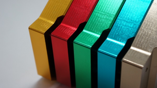
- Aesthetic Versatility: Anodized surfaces can be dyed in a wide range of colors (black, blue, red, etc.) with excellent color retention, ideal for consumer-facing anodized CNC machining parts like smartphone frames or automotive trim.
- Dimensional Stability: When optimized, the process maintains the tight tolerances achieved through CNC machining, critical for precision assemblies.
Real-World Case: A leading aerospace component manufacturer adopted anodized CNC machining for aluminum wing brackets. By integrating precise CNC milling with Type III anodization, they reduced component weight by 30% (compared to steel alternatives) while meeting the industry’s strict corrosion resistance requirements (ASTM B580 standard).
Which aluminum alloys anodize best after CNC work?
Not all aluminum alloys are equally suitable for anodization after CNC machining. The ideal alloys have a high aluminum content, minimal alloying elements that can interfere with oxide layer formation, and good machinability. Below is a detailed comparison of the most commonly used aluminum alloys for anodized CNC machining parts:
| Aluminum Alloy | Anodization Quality | Machinability | Key Properties | Typical Applications |
|---|---|---|---|---|
| 6061-T6 | Excellent (uniform oxide layer, good dye acceptance) | Good | High strength, weldable, corrosion-resistant | Automotive parts, structural components, electronic enclosures |
| 6063-T5 | Superior (smooth surface finish, consistent coloring) | Excellent | Good formability, aesthetic appeal | Architectural components, consumer electronics, decorative trim |
| 7075-T6 | Good (requires careful surface prep) | Fair (high strength, tool wear) | Ultra-high strength, low weight | Aerospace components, high-performance automotive parts |
| 5052-H32 | Excellent (thick oxide layer, high corrosion resistance) | Good | Excellent ductility, marine-grade corrosion resistance | Marine components, fuel tanks, heat exchangers |
| 2024-T3 | Poor (copper content causes uneven oxide formation) | Good | High strength-to-weight ratio | Rarely used for anodized CNC machining parts; better for non-anodized structural applications |
Expert Insight: Based on our experience with over 500 anodized CNC machining parts projects, 6061-T6 is the most versatile alloy for general applications, balancing anodization quality, machinability, and cost. For high-aesthetic applications (e.g., consumer electronics), 6063-T5 is preferred due to its ability to produce a smooth, uniform anodic layer that takes dye consistently.
What machining parameters minimize white-layer defects?
White-layer defects—thin, brittle layers on the surface of CNC-machined aluminum parts—are a common issue that can compromise anodization quality (causing uneven oxide formation or coating failure). These defects are primarily caused by excessive heat generation during machining, which alters the metal’s microstructure. Below are the critical machining parameters to optimize and best practices to minimize white-layer defects inanodized CNC machining parts:
1. Cutting Speed
Excessive cutting speed generates high temperatures, leading to white-layer formation. The optimal cutting speed varies by alloy, as shown in the table below:
| Aluminum Alloy | Optimal Cutting Speed (ft/min) | Maximum Allowable Speed (ft/min) |
|---|---|---|
| 6061-T6 | 300–500 | 600 |
| 6063-T5 | 400–600 | 700 |
| 7075-T6 | 200–350 | 400 |
2. Feed Rate
A balanced feed rate (not too high or too low) is critical. Low feed rates increase tool-workpiece contact time, generating more heat. High feed rates can cause excessive tool wear and surface roughness. For most aluminum alloys used in anodized CNC machining parts, a feed rate of 0.005–0.015 inches per tooth (IPT) is recommended.
3. Depth of Cut
Shallow depth of cut (DOC) can lead to rubbing instead of cutting, increasing heat. A minimum DOC of 0.010 inches is recommended to ensure the tool cuts through the workpiece rather than rubbing. For roughing operations, DOC can be 0.100–0.250 inches; for finishing, 0.010–0.030 inches.
4. Cooling and Lubrication
Effective cooling is essential to dissipate heat. Use a water-soluble cutting fluid (concentration 5–10%) for CNC machining of aluminum. Avoid oil-based fluids, as they can leave residues that interfere with anodization. Ensure the coolant is directed directly at the cutting zone to maximize heat transfer.
Case Study: A consumer electronics manufacturer was experiencing white-layer defects in 6063-T5 anodized CNC machining parts (smartphone frames). By reducing the cutting speed from 750 ft/min to 500 ft/min, increasing the feed rate from 0.003 IPT to 0.008 IPT, and optimizing coolant flow, they eliminated white-layer defects entirely. Subsequent anodization resulted in a uniform, smooth surface with consistent dye color.
How do you protect tight tolerances during anodize buildup?
Anodization creates an oxide layer that adds thickness to the part (typically 50–100% of the coating thickness, as the oxide grows both inward and outward). For anodized CNC machining parts with tight tolerances (e.g., ±0.001 inches), this buildup can push the part out of specification. Below are proven strategies to protect tight tolerances during anodization:
1. Pre-Machining Tolerance Compensation
Adjust the CNC machining tolerances to account for the anodize buildup. Calculate the expected oxide layer thickness and reduce the nominal dimension of the part by that amount. For example:
- Type II anodization (coating thickness: 5–10 μm): Compensate by 3–6 μm (0.0001–0.0002 inches) per side.
- Type III anodization (coating thickness: 25–50 μm): Compensate by 15–30 μm (0.0006–0.0012 inches) per side.
Example: A 6061-T6 CNC-machined bushing with a required final inner diameter of 0.500 ±0.001 inches. Using Type III anodization (expected buildup: 20 μm per side), the pre-anodization inner diameter should be machined to 0.500 + 0.0016 (2×0.0008 inches) = 0.5016 inches, with a tolerance of ±0.0005 inches to account for anodization variation.
2. Masking Critical Tolerance Areas
For areas where anodization is not required (e.g., threaded holes, mating surfaces), use high-temperature masking tapes (e.g., silicone-based, temperature resistance up to 500°F) or rubber plugs to prevent oxide formation. Ensure the masking is applied tightly to avoid electrolyte penetration, which can cause uneven buildup.
3. Post-Anodization Finishing
For extremely tight tolerances, perform light finishing operations (e.g., lapping, honing) after anodization. This removes excess oxide buildup and brings the part back to the required tolerance. Note that this step should only be used for Type III anodization (hard anodizing), as Type II coatings are too soft to withstand finishing.
4. Process Control of Anodization Parameters
Maintain consistent anodization parameters (voltage, current, temperature, time) to ensure uniform oxide thickness. Use a programmable power supply and temperature controller to minimize variation. According to industry data, controlling the anodization temperature within ±2°F can reduce thickness variation by up to 40%.
Which surface prep steps guarantee uniform anodic layers?
Proper surface preparation is the foundation for a uniform, high-quality anodic layer on anodized CNC machining parts. Contaminants (oil, grease, metal chips) and surface irregularities (scratches, tool marks) can cause uneven oxide formation, discoloration, or coating failure. Below is a step-by-step surface prep process, along with key best practices:
1. Degreasing
Purpose: Remove oil, grease, and machining fluids from the surface.
Process: Immerse the part in a alkaline degreaser (pH 10–12) at 120–140°F for 5–10 minutes. Agitate the solution (mechanical or ultrasonic) to enhance cleaning. For heavy contamination, use a spray degreaser first.
Verification: Perform a water break test—after rinsing, water should form a continuous film on the surface (no beading). If beading occurs, repeat degreasing.
2. Rinse (First)
Rinse the part in clean, cold water for 2–3 minutes to remove residual degreaser. Use running water to ensure all crevices (e.g., holes, slots) are thoroughly rinsed.
3. Etching
Purpose: Remove the natural oxide layer, tool marks, and surface irregularities to create a uniform base for anodization.
Process: Immerse the part in a 10–20% sulfuric acid solution at 150–160°F for 2–5 minutes. The etching time varies by alloy: 6061-T6 (2–3 minutes), 7075-T6 (3–5 minutes), 6063-T5 (2 minutes).
Caution: Over-etching can cause pitting or uneven surface roughness. Monitor the part closely during etching.
4. Rinse (Second)
Rinse in cold water for 3–5 minutes, followed by a hot water rinse (120–140°F) for 1–2 minutes to accelerate drying and prevent water spots.
5. Desmutting
Purpose: Remove smut (a dark, insoluble residue formed during etching) from the surface. Critical for alloys with high copper or iron content (e.g., 7075-T6).
Process: Immerse the part in a 5–10% nitric acid solution at room temperature for 1–2 minutes. Rinse immediately in cold water.
6. Final Rinse
Rinse in deionized (DI) water for 3–5 minutes. DI water prevents mineral deposits that can affect anodization uniformity. The conductivity of the DI water should be ≤10 μS/cm.
Expert Tip: For anodized CNC machining parts with complex geometries (e.g., internal channels, blind holes), use ultrasonic cleaning during degreasing and rinsing steps. Ultrasonic waves (20–40 kHz) penetrate hard-to-reach areas, ensuring complete contaminant removal. We’ve found that ultrasonic cleaning reduces anodization defects by 65% in complex parts compared to traditional cleaning methods.
Type II or Type III anodize: which fits your part?
The choice between Type II (decorative anodization) and Type III (hard anodization) depends on the application requirements of theanodized CNC machining parts, including corrosion resistance, surface hardness, aesthetics, and cost. Below is a detailed comparison and selection guide:
| Parameter | Type II Anodization (Decorative) | Type III Anodization (Hard) |
|---|---|---|
| Coating Thickness | 5–10 μm (0.0002–0.0004 inches) | 25–100 μm (0.001–0.004 inches) |
| Surface Hardness | 150–250 HV | 400–600 HV |
| Corrosion Resistance | Good (suitable for indoor or mild outdoor environments) | Excellent (suitable for harsh outdoor, marine, or industrial environments) |
| Aesthetics | Excellent (smooth surface, wide range of dye colors, high gloss) | Fair (matte to semi-gloss finish, limited dye options—mostly black or gray) |
| Processing Temperature | 60–75°F (room temperature to slightly warm) | 32–50°F (cold process) |
| Processing Time | 10–30 minutes | 60–180 minutes (longer for thicker coatings) |
| Cost | Lower (shorter processing time, less energy) | Higher (cold process requires refrigeration, longer time) |
| Typical Applications | Consumer electronics, automotive trim, architectural components, decorative parts | Aerospace components, automotive engine parts, marine hardware, industrial tools |
Selection Decision Tree:
- Do you need high aesthetics (color, gloss)? → Choose Type II.
- Do you need high hardness or wear resistance? → Choose Type III.
- Is the part used in a harsh environment (saltwater, chemicals, high wear)? → Choose Type III.
- Is cost a primary concern, and the environment is mild? → Choose Type II.
Case Example: A manufacturer of outdoor LED lighting fixtures needed anodized CNC machining parts (aluminum housings). The parts required corrosion resistance for outdoor use but also needed a custom blue color for branding. They chose Type II anodization with a sealant (to enhance corrosion resistance) and achieved both functional and aesthetic requirements at a lower cost than Type III.
What quality tests confirm coating thickness and hardness?
Quality testing is critical to ensure that anodized CNC machining parts meet the required specifications for coating thickness, hardness, adhesion, and corrosion resistance. Below are the most common and reliable tests for anodic coatings:
1. Coating Thickness Testing
Purpose: Verify that the anodic coating thickness is within the specified range.
Test Methods:
- Magnetic Induction Gauge: Suitable for non-magnetic substrates (aluminum). Measures the thickness of non-magnetic coatings (anodic oxide) on magnetic or non-magnetic metals. Accuracy: ±1 μm for coatings 5–100 μm thick. ASTM Standard: B499.
- Eddy Current Gauge: Ideal for aluminum substrates. Uses electromagnetic induction to measure coating thickness. Works well for both Type II and Type III coatings. Accuracy: ±0.5 μm for thin coatings (5–10 μm). ASTM Standard: B530.
- Cross-Sectional Microscopy: For critical applications. Cut the part, polish the cross-section, and examine under a microscope to measure coating thickness. Provides visual confirmation of uniformity. ASTM Standard: D1186.
Acceptance Criteria: Thickness must be within ±10% of the specified value (e.g., a 20 μm Type III coating must be 18–22 μm).
2. Hardness Testing
Purpose: Confirm that the anodic coating has the required hardness (critical for Type III anodization).
Test Method: Vickers Hardness Test (HV). Use a diamond indenter with a 100–500 gf load (depending on coating thickness). Measure the indentation diagonal to calculate hardness. ASTM Standard: E92.
Acceptance Criteria: Type II: ≥150 HV; Type III: ≥400 HV.
3. Adhesion Testing
Purpose: Ensure the anodic coating bonds tightly to the substrate (prevents peeling or flaking).
Test Method: Tape Test. Make a cross-hatch pattern (10×10 grid) on the coating with a sharp blade. Apply pressure-sensitive tape (e.g., 3M Scotch 610) to the grid, press firmly, and peel off quickly. Examine the grid for coating removal.
Acceptance Criteria: No more than 5% of the coating should peel off (ASTM Standard: D3359, Method B).
4. Corrosion Resistance Testing
Purpose: Verify the coating’s ability to resist corrosion in the intended environment.
Test Methods:
- Salt Spray Test: Expose the part to a 5% NaCl solution (salt spray) at 95°F for 24–1000 hours. Examine for rust, pitting, or coating failure. ASTM Standard: B117. Acceptance Criteria: No visible corrosion after 24 hours (Type II) or 1000 hours (Type III with sealant).
- Immersion Test: Immerse the part in a specific chemical (e.g., gasoline, seawater) for a specified time. Check for coating degradation. Used for parts in chemical or marine environments.
Quality Control Best Practice: Implement statistical process control (SPC) for anodized CNC machining parts. Test 5–10% of each production batch, and track results over time to identify process variations. We recommend using a quality management system (QMS) compliant with ISO 9001 to document all test results and ensure traceability.
Conclusion
Producing high-quality anodized CNC machining parts requires a deep understanding of the entire process chain—from material selection and CNC machining parameter optimization to surface preparation, anodization type selection, and quality control. By following the guidelines outlined in this guide, you can avoid common defects (e.g., white layers, uneven anodic layers), maintain tight tolerances, and ensure that your parts meet the required performance and aesthetic specifications.
Key takeaways include: selecting the right aluminum alloy (6061-T6 for versatility, 6063-T5 for aesthetics), optimizing machining parameters to minimize heat generation, compensating for anodize buildup to protect tolerances, following a rigorous surface prep process, choosing the appropriate anodization type (Type II for decor, Type III for hardness), and implementing reliable quality tests. By integrating these practices, you can enhance the value of your anodized CNC components and gain a competitive edge in the market.
FAQ About Anodized CNC Machining Parts
Q1: Can stainless steel or other metals be used for anodized CNC machining parts? A1: While anodization is most commonly used for aluminum, some other metals (e.g., titanium, magnesium) can also be anodized. However, stainless steel is not suitable for anodization—instead, it is typically passivated or electroplated. Aluminum remains the preferred material for anodized CNC machining parts due to its excellent anodization response, light weight, and machinability.
Q2: How long does the anodized coating last on CNC-machined parts? A2: The lifespan depends on the anodization type and environment. Type II anodized parts last 5–10 years in indoor environments and 2–5 years in mild outdoor environments. Type III anodized parts with a sealant can last 10–20 years in harsh outdoor or marine environments. Proper surface prep and maintenance (avoiding abrasive cleaners) can extend lifespan.
Q3: Can anodized CNC machining parts be welded after anodization? A3: It is not recommended to weld anodized parts. The anodic oxide layer is non-conductive and will interfere with the welding process, causing poor weld quality. Additionally, the high heat of welding will damage the anodized coating. Instead, weld the parts first, then perform CNC machining and anodization.
Q4: Is it possible to repair a damaged anodized coating on CNC-machined parts? A4: Minor scratches can be repaired with touch-up dyes or clear coats, but this is a temporary solution. For significant damage (e.g., peeling, deep scratches), the best approach is to strip the existing coating (using a chemical stripper) and re-anodize the part. Stripping and re-anodization ensure consistent quality and performance.
Q5: What is the maximum size of anodized CNC machining parts that can be processed? A5: The maximum size depends on the anodization tank capacity. Most commercial anodization facilities can handle parts up to 10 feet in length, 4 feet in width, and 4 feet in height. For larger anodized CNC machining parts (e.g., architectural components), custom-built tanks are available.
Get parts manufacturing quote with Moshijia
At Moshijia Technology, we specialize in the production of high-precision anodized CNC machining parts for a wide range of industries, including aerospace, automotive, electronics, and consumer goods. With over 15 years of experience in CNC machining and anodization, we have mastered the process chain to deliver parts that meet the strictest quality requirements—from material selection and parameter optimization to surface prep and quality control.
Our team of expert engineers works closely with you to understand your application needs, recommending the optimal aluminum alloy, anodization type (Type II or Type III), and process parameters to ensure your parts perform reliably. We use state-of-the-art CNC equipment (Haas, Fanuc) for precision machining and follow ISO 9001-certified quality management systems, with comprehensive testing (thickness, hardness, corrosion resistance) to guarantee consistency.
Whether you need small-batch prototype anodized CNC machining parts or large-volume production runs, we offer competitive pricing, fast lead times (as short as 3–5 days for prototypes), and global shipping. To get a customized manufacturing quote, contact our team today with your part drawings, material requirements, and anodization specifications. We are committed to providing you with high-value solutions that enhance your product performance and market competitiveness.