Manufacturers relying on metal CNC machining often face costly hurdles: tight-tolerance CNC parts that fail to meet aerospace or medical standards, tool breakage when machining tough metals like titanium, or uneven Ra surface finish that requires rework. These issues arise from gaps in understanding precision requirements, material-specific machining strategies, and optimal tooling setups. This guide demystifies the key elements of metal CNC machining to help you deliver high-quality parts consistently.
1. Precision Metal CNC Machining: Meeting the Strictest Industry Standards
Precision is non-negotiable in industries like aerospace, medical, and optics—where micron-level accuracy can mean the difference between a functional device and a failed product. Precision metal CNC machining encompasses processes tailored to achieve ultra-tight specs and flawless finishes.
| Precision Level | Key Processes | Typical Tolerance Range | Industry Applications |
| Standard Precision | Basic 3-axis milling | ±0.01mm – ±0.05mm | Automotive brackets, consumer electronics |
| High Precision | high-precision milling, 5-axis machining | ±0.001mm – ±0.01mm | Medical devices (e.g., surgical tools), optical components |
| Ultra-Precision | 5-axis precision machining, micro-drilling metals | ±0.0005mm – ±0.001mm | Aerospace components, optical lenses |
aerospace-grade machining and medical-device CNC demand the highest precision, often requiring mirror-surface finishes (Ra < 0.2μm) to reduce friction and ensure biocompatibility. For example, optical-component machining relies on specialized cutting tools and vibration-dampened machines to avoid surface defects that distort light.
2. CNC Milling & Turning for Metals: Choosing the Right Process
The choice between milling and turning depends on part geometry, material, and production volume. CNC milling & turning for metals offer versatile solutions for everything from simple shafts to complex 3D parts.
| Machining Type | Key Equipment | Best for Part Geometry | Typical Materials Processed |
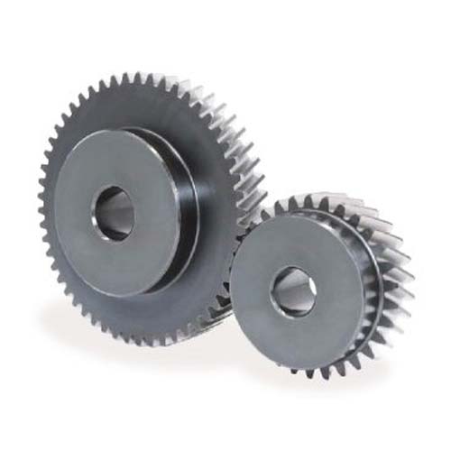
| CNC Milling | 3-axis CNC milling, 5-axis simultaneous milling, vertical machining centers, horizontal CNC milling | Complex 3D shapes (pockets, bosses), flat parts | Aluminum, steel, titanium |
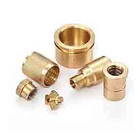
| CNC Turning | CNC turning centers, live-tool lathe, swiss-type CNC turning | Cylindrical parts (shafts, bolts), symmetric components | Brass, copper, stainless steel |
| Mill-Turn | mill-turn machines | Hybrid parts (cylindrical + 3D features) | Inconel, tool steel |
5-axis simultaneous milling excels at complex parts like aerospace turbine blades, as it reduces setup time by 40–60% compared to 3-axis milling. Swiss-type CNC turning is ideal for small, high-precision parts (e.g., medical needles) with diameters as small as 0.5mm. When using milling tools, face milling cutters are best for flat surfaces, while optimizing carbide insert speeds & feeds prevents overheating—e.g., 1,200–1,800 RPM for steel with carbide inserts.
3. Material-Specific CNC Guides: Mastering Tough and Soft Metals
Each metal has unique properties that impact machining difficulty, tool selection, and parameters. Ignoring material specifics leads to tool wear, poor precision, or even safety risks (e.g., with magnesium).
| Metal Material | Key Machining Tips | Recommended Tools | Typical Challenges |
| Aluminum 6061-T6 | High speeds (10,000–20,000 RPM), good chip evacuation | Carbide end mills (2-flute) | Chip adhesion (solve with coolant) |
| Stainless Steel 316L | Slow speeds (800–1,500 RPM), high coolant pressure | Coated carbide tools | Work hardening (avoid excessive heat) |
| Titanium Ti-6Al-4V | Low feed rates (50–200 mm/min), rigid setups | Solid carbide end mills | High cutting forces (risk of tool breakage) |
| Copper | Sharp tools, low friction coatings | Single-flute carbide cutters | Ductility (burrs form easily) |
| Brass | Fast speeds (2,000–5,000 RPM), brass free-cutting | HSS or carbide tools | Minimal—brass is highly machinable |
| Inconel 718 | Inconel 718 strategies: low speeds (300–800 RPM), trochoidal toolpaths | Ceramic or coated carbide | High heat resistance (shortens tool life) |
| Magnesium | magnesium safety: dry machining (no water-based coolant), fire suppression | Sharp HSS tools | Fire risk (use mineral oil coolant) |
For refractory metals (e.g., tungsten), use slow speeds, high rigidity, and diamond-coated tools to overcome extreme hardness. Tool steel heat treatment (e.g., quenching) improves part strength but requires pre-heat treatment machining to avoid brittleness.
4. Tooling & Cutting Parameters: Maximizing Efficiency and Tool Life
Poor tooling choices and incorrect parameters are the top causes of wasted material and delayed projects. Tooling & cutting parameters for metal CNC machining must align with material, precision, and process.
Key Tooling & Parameter Tips:
- Carbide end-mill coatings: Use TiAlN coatings for steel/titanium (resists heat) and diamond-like carbon (DLC) for aluminum/copper (reduces friction).
- HSS vs carbide: HSS is cheaper for low-volume, soft metals (e.g., brass); carbide is better for high-volume, hard metals (e.g., stainless steel) and lasts 3–5x longer.
- Cutting speed formulas: Use the formula: Cutting Speed (m/min) = (π × Tool Diameter × RPM) / 1,000. For example, a 10mm carbide tool in aluminum needs ~150 m/min → RPM = (150 × 1,000) / (π × 10) ≈ 4,775.
- Feed per tooth calculation: Aim for 0.05–0.15 mm/tooth for carbide tools (adjust down for hard metals).
- Depth-of-cut limits: For aluminum, up to 2x tool diameter; for steel, up to 1x tool diameter (prevents tool deflection).
- Coolant selection: Water-soluble coolant for aluminum/steel; mineral oil for magnesium/copper; air blast for precision parts (avoids coolant stains).
- Tool life optimization: Use tool wear monitoring (e.g., laser sensors) to replace tools before failure—this reduces scrap by 25–30%.
- Trochoidal tool paths: Ideal for hard metals (e.g., Inconel) as they reduce cutting forces and heat, extending tool life by 40%.
5. Surface Finish & Post-Machining: Perfecting the Final Product
A high-quality surface finish improves part performance (e.g., reducing corrosion) and aesthetics. Surface finish & post-machining steps vary by industry and application.
| Post-Processing Step | Result | Ideal For |
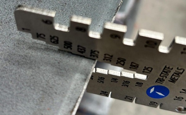
| Ra surface finish chart | Measure roughness (Ra 0.1–12.5μm) | All parts (quality control) |
| Deburring CNC parts | Remove sharp edges, burrs | Medical devices, consumer products |
| Electropolishing stainless | Smooth, corrosion-resistant surface | Food processing equipment, implants |
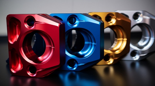
| Anodizing after machining | Colored, protective layer | Aluminum parts (outdoor use) |
| Passivation process | Enhances stainless steel corrosion resistance | Aerospace, marine parts |
| Shot-peening edges | Strengthens surfaces (reduces fatigue) | Automotive springs, turbine blades |
| Micro-blasting aluminum | Matte, uniform finish | Electronic enclosures |
| Chemical film coatings | Thin, adhesive layer (e.g., chromate) | Military, aerospace parts |
| Laser marking metals | Permanent, high-contrast labels | Medical tools, serial numbers |
| Edge rounding | Prevents cracking, improves safety | Machinery components |
For mirror-surface finishes (Ra < 0.2μm), follow machining with polishing (using 1,000–3,000 grit sandpaper) or lapping.
6. CAD/CAM & Programming: Streamlining the Machining Workflow
Efficient CAD/CAM & programming reduces setup time, minimizes errors, and optimizes toolpaths—critical for high-volume or complex parts.
Key CAD/CAM Tips:
- Fusion 360 toolpath and Mastercam dynamic milling: Use these for adaptive clearing (reduces tool wear by 30%) and rest machining (cleans up leftover material from roughing).
- G-code for metals: Simplify programming with CAM post processors (e.g., for Fanuc or Haas machines) to avoid syntax errors.
- Simulation & verification: Use software (e.g., VERICUT) to test toolpaths virtually—this prevents collisions that damage machines or parts.
- Tool library setup: Create a centralized library with tool dimensions, coatings, and recommended parameters to ensure consistency across projects.
- Macro programming: Automate repetitive tasks (e.g., hole drilling) to save 15–20% of programming time.
- Industry 4.0 integration: Connect CAM software to CNC machines for real-time data sharing (e.g., tool wear alerts) to boost productivity.
Moshijia Technology’s Perspective
At Moshijia Technology, we tailor metal CNC machining to solve your unique challenges. For aerospace-grade machining or medical-device CNC, we use 5-axis machines for micron-level accuracy and implement tool wear monitoring to ensure consistency. Our team optimizes parameters—e.g., trochoidal paths for Inconel 718 and high-speed setups for aluminum 6061-T6—to cut lead times by 25%. We also offer end-to-end support, from CAD design to electropolishing stainless or anodizing, delivering ready-to-use parts that meet the strictest standards.
FAQ
- What’s the difference between 3-axis and 5-axis CNC milling for metals?
3-axis CNC milling works for simple 2D/3D parts (e.g., flat brackets) with one setup, while 5-axis simultaneous milling handles complex, multi-angle parts (e.g., turbine blades) in one run—reducing setup time and improving precision.
- How do I choose between HSS and carbide tools for metal CNC machining?
Use HSS tools for low-volume projects with soft metals (e.g., brass, aluminum) to save cost. Choose carbide tools for high-volume runs, hard metals (e.g., stainless steel, titanium), or when needing longer tool life and faster speeds.
- What post-processing step is best for improving stainless steel corrosion resistance?
Passivation process is ideal—it removes free iron from the surface and forms a protective oxide layer, enhancing corrosion resistance for stainless steel parts used in marine, medical, or food industries. For a smoother finish, pair passivation with electropolishing stainless.