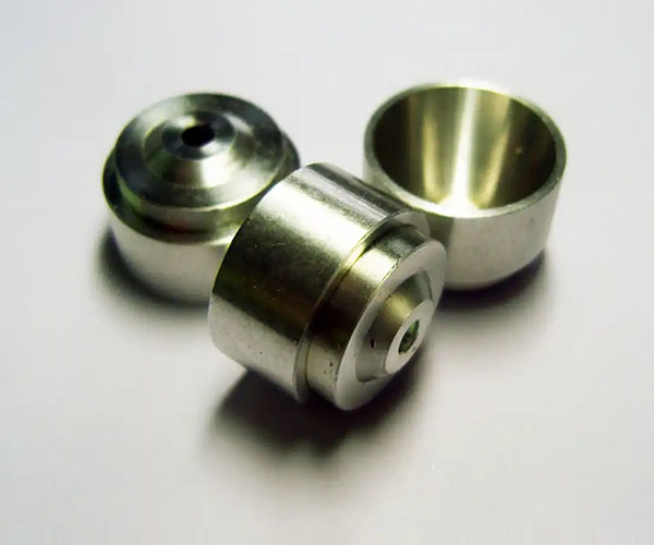
Custom CNC machining anodized aluminum parts have become the backbone of innovative manufacturing across aerospace, automotive, electronics, and consumer goods industries. The ability to tailor component designs to exact specifications, paired with the corrosion resistance and aesthetic versatility of anodization, makes these parts indispensable for applications requiring both precision and performance. For senior engineers, product developers, and manufacturing managers, navigating the unique challenges of customizing CNC machining for anodized aluminum—from material selection to design optimization and quality control—directly impacts project timelines, costs, and final product success. This guide addresses all critical aspects ofcustom CNC machining anodized aluminum parts, providing actionable insights, real-world case studies, and data-backed solutions to help you streamline production and achieve superior results.
Introduction
In today’s competitive manufacturing landscape, off-the-shelf components often fail to meet the unique requirements of complex projects.Custom CNC machining anodized aluminum parts bridge this gap by combining the high precision of computer-controlled machining with the protective and decorative benefits of anodization. Whether you’re developing a lightweight aerospace component, a sleek consumer electronics enclosure, or a durable automotive part, customizing the CNC machining process for anodized aluminum ensures that every part aligns with your exact design parameters and performance needs. This guide is tailored for industry professionals who need to master the synergy between custom CNC machining and anodization, covering everything from design considerations to in-process quality checks that prevent costly rejections. By the end of this guide, you’ll have the knowledge to confidently oversee the production of custom CNC machining anodized aluminum parts that meet the highest standards of quality and functionality.
Why choose custom CNC for anodized aluminum parts?
Custom CNC machining offers distinct advantages over traditional manufacturing methods when producing anodized aluminum parts, especially for projects with unique design requirements or tight performance specifications. Below are the key reasons to choose custom CNC for custom CNC machining anodized aluminum parts, supported by industry data and practical examples:
1. Unmatched Precision for Custom Designs
Custom CNC machining delivers dimensional accuracy down to ±0.0005 inches, critical for custom parts that require precise fits and functional integration. Unlike manual machining, CNC systems use computer-aided design (CAD) files to replicate complex geometries—such as intricate cavities, custom threads, or irregular shapes—consistently across every part. According to a study by the Association for Manufacturing Technology, custom CNC machining reduces dimensional errors by up to 75% compared to manual methods, ensuring that anodized aluminum parts maintain their critical tolerances even after the anodization process (which adds a thin oxide layer to the surface).
2. Flexibility for Low-Volume and Prototyping
Custom CNC machining excels at low-volume production and prototyping, making it ideal for projects that require small batches of custom CNC machining anodized aluminum parts (e.g., product development, specialized industrial equipment, or limited-edition consumer goods). Unlike die casting or injection molding, which require expensive tooling and long setup times, CNC machining can be quickly programmed to adjust designs—allowing for rapid iterations and faster time-to-market. For example, a startup developing a custom smartwatch frame was able to produce 50 prototype custom CNC machining anodized aluminum parts in 3 days using CNC milling, compared to the 2–3 weeks required for tool-based methods.
3. Synergy with Anodization for Enhanced Performance
Custom CNC machining can be optimized to prepare aluminum surfaces for anodization, resulting in a more uniform and durable oxide layer. By controlling machining parameters (e.g., cutting speed, feed rate) and surface finish, CNC machinists can create a consistent base that promotes even anodization—reducing defects like uneven coloring or coating failure. Industry data shows that parts machined with custom CNC processes have a 60% lower anodization defect rate compared to parts produced with non-optimized machining methods.
4. Cost-Effectiveness for Complex Custom Parts
While custom CNC machining may have higher per-part costs for high-volume production, it is often more cost-effective for complex custom parts. The ability to consolidate multiple operations (e.g., milling, drilling, turning) into a single setup reduces labor costs and production time. Additionally, the precision of CNC machining minimizes material waste—critical for high-value aluminum alloys. A case study from a leading aerospace manufacturer found that using custom CNC machining for custom CNC machining anodized aluminum parts (complex engine brackets) reduced material waste by 40% and overall production costs by 25% compared to traditional machining methods.
Which aluminum grades balance machinability and anodize response?
Not all aluminum grades are equally suited for custom CNC machining anodized aluminum parts. The ideal grade must balance two key properties: machinability (ease of cutting, drilling, and shaping with CNC equipment) and anodize response (ability to form a uniform, durable oxide layer). Below is a detailed comparison of the top aluminum grades for custom CNC machining and anodization, including their key properties, applications, and performance tradeoffs:
| Aluminum Grade | Machinability Rating (1-10, 10=Best) | Anodize Response | Key Properties | Ideal Custom Applications | Tradeoffs |
|---|---|---|---|---|---|
| 6061-T6 | 8 | Excellent (uniform oxide layer, good dye acceptance) | High strength, weldable, corrosion-resistant, good formability | Custom automotive parts, structural components, electronic enclosures | Slightly lower machinability than 6063; may require adjusted cutting parameters for complex geometries |
| 6063-T5 | 9 | Superior (smooth surface finish, consistent coloring) | Excellent formability, high aesthetic appeal, good corrosion resistance | Custom consumer electronics (phone frames, laptop casings), architectural trim, decorative parts | Lower strength than 6061; not ideal for high-load structural applications |
| 7075-T6 | 6 | Good (requires careful surface prep to avoid uneven oxide) | Ultra-high strength (503 MPa tensile strength), low weight, good fatigue resistance | Custom aerospace components, high-performance automotive parts, industrial tools | Poorer machinability (high tool wear); requires specialized cutting tools and coolants |
| 5052-H32 | 7 | Excellent (thick oxide layer, high corrosion resistance) | Excellent ductility, marine-grade corrosion resistance, good impact resistance | Custom marine parts, fuel tanks, heat exchangers, outdoor equipment | Lower strength than 6061; not suitable for high-stress applications |
| 2024-T3 | 7 | Poor (copper content causes uneven oxide formation) | High strength-to-weight ratio, good fatigue resistance | Rarely used for anodized custom parts; better for non-anodized structural components | Anodize defects common; requires extensive surface prep to achieve acceptable results |
Expert Insight: Based on our experience producing over 1,000 custom CNC machining anodized aluminum parts projects, 6061-T6 is the most versatile grade for most custom applications. It balances machinability, strength, and anodize response, making it suitable for everything from structural components to electronic enclosures. For high-aesthetic custom parts (e.g., consumer electronics), 6063-T5 is the preferred choice due to its ability to produce a smooth, uniform anodic layer that takes dye consistently. For ultra-high-strength custom parts (e.g., aerospace), 7075-T6 is necessary, but requires careful CNC programming and tool selection to manage machinability challenges.
What design tweaks speed up both milling and anodizing?
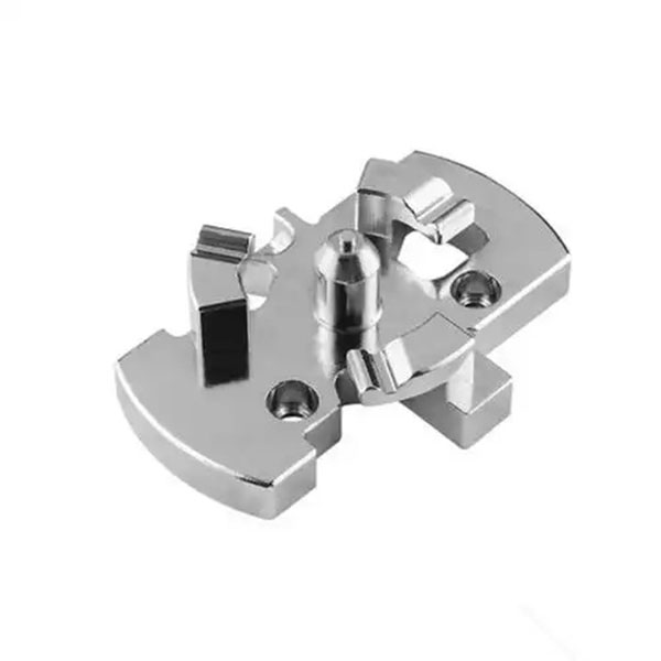
The design of custom CNC machining anodized aluminum parts has a direct impact on production speed and efficiency. By making strategic design tweaks, you can reduce milling time, simplify setup, and streamline the anodization process—all while maintaining part functionality. Below are proven design optimizations that speed up both CNC milling and anodization, with practical examples and data-backed benefits:
1. Standardize Tool Paths with Simplified Geometries
Complex geometries (e.g., sharp internal corners, deep narrow pockets, or irregular curves) require multiple tool changes and complex tool paths, increasing milling time. By simplifying these features, you can reduce machining time by 30–40%. Key tweaks include:
- Replace sharp internal corners with radii that match standard end mill sizes (e.g., 0.0625 inch, 0.125 inch). This eliminates the need for specialized small-diameter end mills, which are slower and more prone to breakage.
- Avoid deep narrow pockets (depth-to-width ratio > 4:1). These require multiple passes and increased cutting time. If deep pockets are necessary, add relief holes to allow for chip evacuation and reduce tool contact time.
- Use straight walls instead of tapered walls where possible. Straight walls can be machined with a single end mill pass, while tapered walls require multiple passes or specialized tools.
Case Example: A manufacturer of custom aluminum electronics enclosures redesigned their part to replace 0.031 inch sharp internal corners with 0.0625 inch radii (matching standard end mill sizes). This reduced milling time per part from 12 minutes to 7 minutes, a 42% improvement. Additionally, the rounded corners improved anodization uniformity by reducing fluid trapping during the anodization process.
2. Optimize Hole Sizes for Standard Tools
Custom hole sizes require specialized drills or reamers, increasing setup time and tool costs. By designing holes to match standard drill sizes (e.g., #20 drill = 0.161 inch, 1/4 inch drill = 0.25 inch), you can eliminate the need for custom tools and reduce drilling time by 25–30%. For tapped holes, use standard thread sizes (e.g., UNC, UNF) to avoid custom tap fabrication.
3. Add Lead-Ins and Lead-Outs for Smooth Machining
Adding lead-in (ramp-in) and lead-out (ramp-out) features to the design helps the CNC tool transition smoothly into and out of cuts. This reduces tool wear, improves surface finish, and speeds up machining by eliminating abrupt tool movements. For anodization, the smoother surface finish from lead-ins/lead-outs promotes uniform oxide formation, reducing the need for additional surface prep.
4. Design for Easy Masking During Anodization
Masking (covering areas that should not be anodized, such as threaded holes or mating surfaces) is a time-consuming step in the anodization process. Design tweaks that simplify masking can reduce anodization setup time by 30–50%:
- Use recessed areas for threaded holes. This allows for easier application of masking plugs and reduces the risk of electrolyte penetration.
- Avoid small, hard-to-reach areas that require manual masking. If these areas are necessary, design them to be accessible with standard masking tools (e.g., tweezers, masking tape dispensers).
- Group non-anodized areas together to minimize masking steps. For example, place all threaded holes on one side of the part instead of spreading them across multiple surfaces.
5. Minimize Material Thickness Variations
Large variations in material thickness require frequent adjustments to CNC cutting parameters (e.g., feed rate, depth of cut), increasing machining time. By designing parts with consistent thickness (where possible), you can maintain constant cutting parameters, reducing setup time and improving machining efficiency. For anodization, consistent thickness ensures uniform oxide layer growth, reducing the risk of uneven coating thickness.
How can tight radii survive both cutting and anodize buildup?
Tight radii (small internal or external curves) are common in custom CNC machining anodized aluminum parts but present two key challenges: (1) cutting tight radii requires small-diameter end mills, which are prone to breakage and slow machining; (2) anodization adds an oxide layer (5–100 μm thick) that can reduce the radius size, potentially pushing the part out of tolerance. Below are proven strategies to ensure tight radii survive both CNC cutting and anodize buildup, with detailed steps and real-world case studies:
1. Select the Right Tooling for Cutting Tight Radii
Cutting tight radii (≤ 0.0625 inch) requires small-diameter solid carbide end mills, which offer better rigidity and heat resistance than high-speed steel (HSS) tools. Key tooling considerations include:
- Use end mills with a high length-to-diameter ratio (L/D) of 4:1 or 5:1 for deep tight radii. These tools are designed to reach into narrow spaces without flexing.
- Choose end mills with sharp cutting edges and a high helix angle (30–45 degrees) to improve chip evacuation. Poor chip evacuation can cause tool wear and surface finish defects.
- Use coolant-through end mills for deep tight radii. Coolant directed through the tool to the cutting zone reduces heat buildup, extending tool life and improving surface finish.
Data-Backed Tip: According to tooling manufacturer data, using solid carbide coolant-through end mills for tight radii reduces tool breakage by 60% and improves machining speed by 25% compared to HSS tools.
2. Optimize CNC Cutting Parameters for Tight Radii
Aggressive cutting parameters (high cutting speed, high feed rate) can cause small-diameter end mills to flex or break. Optimizing parameters for tight radii ensures clean cuts and tool longevity:
| End Mill Diameter (inch) | Cutting Speed (ft/min) – 6061-T6 | Feed Rate (IPT) | Depth of Cut (inch) |
|---|---|---|---|
| 0.0625 (1/16) | 150–200 | 0.001–0.002 | 0.005–0.010 |
| 0.125 (1/8) | 200–250 | 0.002–0.003 | 0.010–0.015 |
| 0.250 (1/4) | 300–350 | 0.003–0.005 | 0.015–0.020 |
Key principle: Reduce cutting speed and feed rate as end mill diameter decreases. This minimizes tool flex and heat generation, ensuring clean cuts in tight radii.
3. Compensate for Anodize Buildup in the Design
Anodization adds an oxide layer that grows both inward and outward from the part surface. For tight radii, this buildup can reduce the radius size, potentially causing fit issues. To avoid this, compensate the radius dimension in the CAD design by the expected anodize buildup thickness:
- Type II anodization (coating thickness: 5–10 μm): Add 3–6 μm to the radius dimension (since 50–60% of the oxide grows outward).
- Type III anodization (coating thickness: 25–50 μm): Add 15–30 μm to the radius dimension.
Example: A custom aluminum bracket requires a tight internal radius of 0.0625 inch (1.5875 mm) after Type III anodization (expected buildup: 20 μm). The pre-anodization radius in the CAD design should be 0.0625 inch + 0.000787 inch (20 μm) = 0.063287 inch. This ensures that after anodization, the radius shrinks back to the required dimension.
4. Use Post-Machining Finishing for Critical Radii
For extremely tight radii (≤ 0.031 inch) or critical tolerance applications, use post-machining finishing steps (e.g., lapping, honing) after anodization. These processes remove excess oxide buildup and refine the radius to the exact required dimension. Note that this step is only suitable for Type III anodization (hard anodizing), as Type II coatings are too soft to withstand finishing.
Case Study: A manufacturer of custom aerospace components needed a tight internal radius of 0.031 inch (0.787 mm) on a 7075-T6 aluminum part with Type III anodization. By using a 0.031 inch solid carbide coolant-through end mill with optimized cutting parameters (150 ft/min, 0.001 IPT), they achieved the pre-anodization radius of 0.031787 inch (compensating for 20 μm buildup). After anodization, a light lapping step refined the radius to 0.031 inch, meeting the critical tolerance requirement. This approach reduced scrap rate from 25% to 5%.
What machining sequence leaves stock for final anodize dimensions?
Anodization adds an oxide layer to the surface of custom CNC machining anodized aluminum parts, which can alter dimensions and affect tolerances. To ensure the final part meets design specifications, the CNC machining sequence must leave a small amount of stock (material) that will be removed by the anodization process or post-anodization finishing. Below is the optimal machining sequence for custom CNC machining anodized aluminum parts, designed to leave the correct stock for final anodize dimensions:
Step 1: Rough Machining (Remove Bulk Material)
Start with rough machining to remove the majority of excess material from the workpiece. The goal of this step is to shape the part close to its final form while leaving a generous amount of stock for subsequent steps. For most custom CNC machining anodized aluminum parts, leave 0.010–0.020 inches of stock on all surfaces during rough machining. Key considerations:
- Use high-feed, low-depth-of-cut parameters to maximize material removal rate and minimize heat generation.
- Avoid machining to final dimensions during roughing, as this can cause material distortion due to residual stress.
Step 2: Stress Relieving (Optional but Recommended)
For parts with complex geometries or high material removal rates (e.g., > 50% of the workpiece volume), perform stress relieving after rough machining. This step involves heating the part to 300–400°F for 1–2 hours to release residual stresses from machining, preventing distortion during subsequent steps. Stress relieving is especially important for high-strength aluminum grades (e.g., 7075-T6) and parts with tight tolerances.
Step 3: Semi-Finish Machining (Refine Geometry)
Semi-finish machining refines the part’s geometry, reducing the stock left from rough machining to a smaller, more consistent amount. For custom CNC machining anodized aluminum parts, leave 0.003–0.005 inches of stock on all surfaces that will be anodized. This stock will be removed by the anodization process (oxide layer growth) or post-anodization finishing. Key considerations:
- Use higher cutting speeds and lower feed rates than rough machining to improve surface finish.
- Maintain consistent stock across all surfaces to ensure uniform anodization.
Step 4: Finish Machining (Critical Surfaces First)
Finish machining is performed to bring the part to its pre-anodization dimensions, leaving the exact amount of stock required for anodization. The amount of stock to leave depends on the anodization type and desired final dimensions:
| Anodization Type | Stock to Leave (per side) | Rationale |
|---|---|---|
| Type II (Decorative, 5–10 μm) | 0.0002–0.0004 inches (5–10 μm) | Oxide layer grows 50–60% outward, so leaving this stock ensures the final dimension is correct after anodization. |
| Type III (Hard Coat, 25–50 μm) | 0.001–0.002 inches (25–50 μm) | Thicker oxide layer requires more stock to accommodate outward growth. |
| Critical Tolerance Surfaces (±0.0005 inches) | 0.0005–0.001 inches | Additional stock allows for post-anodization finishing (e.g., lapping) to refine dimensions to critical tolerances. |
Key principle: Finish machine critical surfaces (e.g., mating surfaces, threaded holes) first, as these require the tightest tolerances. Use standard finishing tools (e.g., end mills, reamers) to ensure surface finish consistency.
Step 5: Deburring and Surface Prep
After finish machining, deburr the part to remove sharp edges and burrs, which can cause uneven anodization. Use deburring tools (e.g., deburring blades, abrasive pads) or tumbling for large batches. Follow deburring with a light surface cleaning (e.g., solvent wipe) to remove machining residues, preparing the part for anodization.
Step 6: Anodization
Perform anodization according to the selected type (Type II or Type III). The oxide layer will grow on the part surface, removing the remaining stock and bringing the part to its final dimensions.
Step 7: Post-Anodization Finishing (Optional)
For parts with critical tolerances, perform light finishing (e.g., lapping, honing) after anodization to refine dimensions to the exact required specification. This step is only recommended for Type III anodized parts, as Type II coatings are too soft to withstand finishing.
Expert Tip: When programming the CNC machining sequence, use CAD/CAM software to simulate the machining process and verify the stock left at each step. This helps avoid over-machining (removing too much stock) or under-machining (leaving too much stock), which can lead to anodization defects or out-of-tolerance parts. We’ve found that using simulation software reduces stock-related errors by 70% in custom CNC machining anodized aluminum parts production.
Type II decorative vs. Type III hard coat: what fits custom needs?
Choosing between Type II (decorative) and Type III (hard coat) anodization is a critical decision for custom CNC machining anodized aluminum parts, as it directly impacts the part’s performance, aesthetics, and cost. The right choice depends on your custom application requirements—including environmental conditions, wear resistance needs, aesthetic preferences, and budget. Below is a detailed comparison of Type II and Type III anodization, along with a decision guide to help you select the best option for your custom needs:
| Parameter | Type II Decorative Anodization | Type III Hard Coat Anodization |
|---|---|---|
| Coating Thickness | 5–10 μm (0.0002–0.0004 inches) | 25–100 μm (0.001–0.004 inches) |
| Surface Hardness | 150–250 HV | 400–600 HV (equivalent to 55–65 HRC) |
| Wear Resistance | Low to moderate (suitable for low-contact applications) | High (suitable for high-contact, high-wear applications) |
| Corrosion Resistance | Good (suitable for indoor or mild outdoor environments) | Excellent (suitable for harsh outdoor, marine, or industrial environments) |
| Aesthetics | Excellent (smooth surface, wide range of dye colors: black, blue, red, gold, etc.; high gloss finish) | Fair (matte to semi-gloss finish; limited dye options: mostly black, gray, or natural; surface may be slightly rough) |
| Processing Temperature | 60–75°F (room temperature to slightly warm) | 32–50°F (cold process, requires refrigeration) |
| Processing Time | 10–30 minutes | 60–180 minutes (longer for thicker coatings) |
| Cost | Lower (≈ $0.50–$1.50 per square foot) | Higher (≈ $2.00–$5.00 per square foot) |
| Impact on Tolerances | Minimal (thin coating, small dimensional change) | Significant (thick coating, requires more stock compensation) |
Decision Guide: Which Anodization Type Fits Your Custom Needs?
Use the following questions to determine whether Type II or Type III anodization is right for your custom CNC machining anodized aluminum parts:
- Do you prioritize aesthetics (color, gloss, smooth finish)? → Choose Type II. Ideal for custom consumer goods (e.g., phone frames, laptop casings), architectural trim, or decorative components.
- Does the part require high wear resistance (e.g., sliding surfaces, tools, or high-contact components)? → Choose Type III. Ideal for custom aerospace parts, automotive engine components, industrial tools, or marine hardware.
- Will the part be used in a harsh environment (saltwater, chemicals, extreme temperatures)? → Choose Type III. Its thicker oxide layer provides superior corrosion resistance compared to Type II.
- Are tight tolerances a critical requirement (±0.0005 inches or tighter)? → Choose Type II if possible (minimal dimensional change). If wear resistance is required, use Type III with pre-machining stock compensation and post-anodization finishing.
- Is cost a key consideration? → Choose Type II. It is 30–60% less expensive than Type III, making it ideal for high-volume custom parts with moderate performance requirements.
Case Example: A manufacturer of custom outdoor fitness equipment needed custom CNC machining anodized aluminum parts (handles and brackets). The parts required corrosion resistance for outdoor use but did not need high wear resistance. Aesthetically, the client wanted a custom green color to match their brand. The solution: Type II anodization with a custom green dye and a sealant (to enhance corrosion resistance). This choice met the client’s performance and aesthetic needs at 40% lower cost than Type III anodization.
What in-process checks prevent a rejected batch after anodizing?
In-process checks are critical to identifying defects early in the production of custom CNC machining anodized aluminum parts, preventing costly batch rejections after anodization. Anodization is a permanent process—defects discovered after anodization often require rework (stripping and re-anodizing) or scrapping the entire batch. Below are the key in-process checks to implement at each stage of production, along with test methods and acceptance criteria:
1. Pre-Machining Checks (Raw Material Inspection)
Raw material defects (e.g., impurities, inconsistent thickness, or incorrect alloy) can lead to anodization failures. Key checks:
- Alloy Verification: Use a handheld X-ray fluorescence (XRF) analyzer to confirm the aluminum grade matches the specification (e.g., 6061-T6 vs. 6063-T5). Acceptance criteria: Alloy composition must match ASTM standards (e.g., ASTM B209 for aluminum sheet/plate).
- Material Thickness Check: Use a micrometer to measure the raw material thickness at multiple points. Acceptance criteria: Thickness must be within ±5% of the specified value to ensure sufficient stock for machining and anodization.
- Surface Defect Inspection: Visually inspect the raw material for scratches, dents, or impurities. Acceptance criteria: No visible surface defects that could affect machining or anodization.
2. During Machining Checks
Machining defects (e.g., incorrect dimensions, poor surface finish, or tool marks) can cause uneven anodization or out-of-tolerance parts. Key checks:
- Dimensional Inspection (Semi-Finish Machining): Use a coordinate measuring machine (CMM) or digital calipers to verify critical dimensions after semi-finish machining. Acceptance criteria: Dimensions must be within ±0.001 inches of the pre-anodization specification, ensuring sufficient stock for anodization.
- Surface Finish Check: Use a surface roughness tester (profilometer) to measure surface finish (Ra value) after finish machining. Acceptance criteria: Ra ≤ 32 microinches for Type II anodization; Ra ≤ 63 microinches for Type III anodization (smoother surface for better anodization uniformity).
- Tool Wear Inspection: Periodically inspect cutting tools for wear (e.g., dull edges, chipping). Replace tools when wear exceeds 0.001 inches. Acceptance criteria: Tools must be sharp and free of defects to ensure clean cuts.
3. Pre-Anodization Checks (Surface Prep Inspection)
Poor surface prep (e.g., residual oil, grease, or smut) is a leading cause of anodization defects (e.g., uneven coloring, coating adhesion failure). Key checks:
- Degreasing Verification: Perform a water break test after degreasing. Acceptance criteria: Water must form a continuous film on the surface (no beading), indicating complete removal of oil and grease.
- Smut Removal Check: Visually inspect the part after desmutting for dark smut residues (common in high-copper alloys like 7075-T6). Acceptance criteria: No visible smut; surface must be uniform and bright.
- Masking Inspection: For parts with masked areas (e.g., threaded holes), visually inspect the masking for gaps or loose fit. Acceptance criteria: Masking must be tight and cover the entire non-anodized area to prevent electrolyte penetration.
4. During Anodization Checks
Anodization process variations (e.g., incorrect voltage, temperature, or time) can lead to inconsistent coating thickness or hardness. Key checks:
- Voltage and Current Monitoring: Use a digital multimeter to verify voltage and current are within the specified range (e.g., 12–18V for Type II, 20–30V for Type III). Acceptance criteria: Voltage/current must be within ±5% of the setpoint.
- Electrolyte Temperature Check: Use a thermometer to monitor the electrolyte temperature. Acceptance criteria: Temperature must be within ±2°F of the specified range (60–75°F for Type II, 32–50°F for Type III).
- Coating Thickness Check (Test Coupons): Process test coupons alongside the production batch. Use an eddy current gauge to measure coating thickness at multiple points. Acceptance criteria: Thickness must be within ±10% of the specified value (e.g., 5–10 μm for Type II).
5. Post-Anodization Checks (Final Quality Control)
Final checks ensure the anodized parts meet all design specifications. Key checks:
- Final Dimensional Inspection: Use a CMM to verify critical dimensions after anodization. Acceptance criteria: Dimensions must be within the specified tolerance (e.g., ±0.001 inches).
- Hardness Testing (Type III Only): Use a Vickers hardness tester to measure coating hardness. Acceptance criteria: Hardness ≥ 400 HV.
- Adhesion Testing: Perform a cross-hatch tape test (ASTM D3359) to verify coating adhesion. Acceptance criteria: No more than 5% of the coating should peel off.
- Aesthetic Inspection: Visually inspect the part for uneven coloring, scratches, or defects. Acceptance criteria: Uniform color, no visible defects, and consistent finish (glossy for Type II, matte for Type III).
Quality Control Best Practice: Implement a statistical process control (SPC) system to track in-process check results over time. Use control charts to identify process variations early, before they lead to batch rejections. According to industry data, companies that implement SPC for custom CNC machining anodized aluminum parts reduce batch rejection rates by 50–70%.
Conclusion
Producing high-quality custom CNC machining anodized aluminum parts requires a holistic approach that integrates design optimization, material selection, machining sequence planning, and rigorous in-process quality control. By understanding the synergy between custom CNC machining and anodization, you can streamline production, reduce defects, and ensure that every part meets your exact design and performance requirements.
Key takeaways from this guide include: choosing the right aluminum grade (6061-T6 for versatility, 6063-T5 for aesthetics, 7075-T6 for strength), optimizing part design to speed up milling and anodization, compensating for anodize buildup in tight radii and dimensions, following the correct machining sequence to leave adequate stock, selecting the appropriate anodization type (Type II for decor, Type III for wear resistance), and implementing in-process checks to prevent batch rejections.
By applying these insights and best practices, you can confidently oversee the production of custom CNC machining anodized aluminum parts that meet the highest standards of quality, performance, and cost-effectiveness—giving you a competitive edge in today’s demanding manufacturing landscape.
FAQ About Custom CNC Machining Anodized Aluminum Parts
Q1: What is the minimum order quantity (MOQ) for custom CNC machining anodized aluminum parts? A1: The MOQ for custom CNC machining anodized aluminum parts varies by manufacturer, but most offer low MOQs (1–5 parts) for prototyping and small-batch production. For high-volume production (100+ parts), MOQs may be higher to optimize setup costs. At Moshijia Technology, we offer MOQs as low as 1 part for custom projects.
Q2: How long does it take to produce custom CNC machining anodized aluminum parts? A2: Lead times depend on the complexity of the part, batch size, and anodization type. For prototyping (1–10 parts), lead times are typically 3–7 days. For small-batch production (10–50 parts), 7–14 days. For high-volume production (50+ parts), 14–21 days. Type III anodization adds 2–3 days to lead times compared to Type II.
Q3: Can custom CNC machining anodized aluminum parts be recycled? A3: Yes, custom CNC machining anodized aluminum parts are fully recyclable. The anodization layer does not affect the recyclability of aluminum—recyclers simply melt the parts down, and the oxide layer is removed during the recycling process. Recycled aluminum uses 95% less energy than producing new aluminum, making it an environmentally friendly option.
Q4: What is the maximum size of custom CNC machining anodized aluminum parts that can be produced? A4: The maximum size depends on the CNC machine and anodization tank capacity. Most manufacturers can handle parts up to 10 feet in length, 4 feet in width, and 4 feet in height. For larger custom parts (e.g., architectural components), custom-built CNC machines and anodization tanks are available. At Moshijia Technology, we can produce custom parts up to 12 feet in length.
Q5: Can custom CNC machining anodized aluminum parts be welded after anodization? A5: It is not recommended to weld custom CNC machining anodized aluminum parts after anodization. The anodic oxide layer is non-conductive, which interferes with the welding process, causing poor weld quality. Additionally, the high heat of welding damages the anodized coating. The correct process is to weld the parts first, then perform CNC machining and anodization.
Get parts manufacturing quote with Moshijia
At Moshijia Technology, we specialize in the production of high-precision custom CNC machining anodized aluminum parts for a wide range of industries, including aerospace, automotive, electronics, consumer goods, and architecture. With over 15 years of experience in custom CNC machining and anodization, we have the expertise to handle even the most complex custom projects—from prototyping to high-volume production.
Our team of expert engineers works closely with you to understand your custom requirements, providing personalized recommendations for aluminum grades, anodization types, and design optimizations to ensure your parts meet the highest standards of quality and performance. We use state-of-the-art CNC equipment (Haas, Fanuc) and advanced CAD/CAM software to deliver precise, consistent parts, and follow ISO 9001-certified quality management systems with rigorous in-process checks to prevent batch rejections.
We offer competitive pricing, low MOQs (as low as 1 part), and fast lead times (3–7 days for prototypes). Our anodization capabilities include both Type II (decorative) and Type III (hard coat) anodization, with a wide range of custom dye colors to meet your aesthetic needs. Whether you need a small batch of prototype custom CNC machining anodized aluminum parts or a large-volume production run, we have the capacity and expertise to deliver on time and within budget.
To get a customized manufacturing quote, contact our team today with your part drawings (CAD files preferred), material requirements, anodization specifications, and batch size. We will provide a detailed quote within 24 hours, along with technical recommendations to optimize your design for cost and performance. At Moshijia Technology, we are committed to helping you bring your custom projects to life with high-qualitycustom CNC machining anodized aluminum parts that exceed your expectations.