Introduction
You spend hours dialing in a program. The spindle speeds up. The cut starts. Then you pull the part off and check it with a mic. It’s off by three tenths. The surface looks like sandpaper. You know the machine is good. So what went wrong?
In most cases, it’s the lathe tooling.
Precision work on a lathe is not just about having a good machine. It is about how you select, set up, and maintain your tools. A dull insert, a wrong nose radius, or a loose tool holder can kill your tolerance stack before you even start cutting.
This guide is for machinists and CNC operators who work with tight tolerances and high surface finish requirements. We will walk through every step — from tool selection to cutting parameter tuning — with real data, case comparisons, and actionable steps you can use on your next job.
Whether you run a Haas, a Doosan, or a manual Tormek, the principles here apply. Let’s get into it.
Understanding Lathe Tooling
What Is Lathe Tooling?
Lathe tooling refers to any cutting tool, holder, insert, or accessory used on a lathe to remove material from a workpiece. This includes carbide inserts, tool holders, boring bars, parting tools, and even the collets that grip them.
It is not just the insert. The whole system matters. A cheap insert in a rigid holder can outperform an expensive insert in a wobbly one.
Key Tool Components
Every lathe tool has three main parts:
| Component | Function | Why It Matters for Precision |
|---|---|---|
| Insert | The actual cutting edge (carbide, ceramic, CBN) | Determines material removal rate and finish |
| Tool Holder | Holds the insert in the turret or post | Affects rigidity and vibration |
| Clamping System | Screws, levers, or wedge locks | Controls how secure the insert sits |
A loose clamping system lets the insert shift under load. That shift shows up as chatter marks or dimensional drift.
Tooling and Workpiece Materials
The workpiece material drives every tooling decision. Here is a quick breakdown:
- Mild Steel (1018, 1045): Use coated carbide. TiAlN works best for heat resistance.
- Stainless Steel (304, 316): These are tough. You need a sharp edge and low feed. Ceramic inserts can help here.
- Aluminum (6061, 7075): Sharp geometry, high speed, low pressure. Uncoated carbide or diamond-coated inserts are ideal.
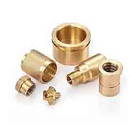
- Brass / Bronze: Free-cutting but gummy. You need good chip evacuation and positive rake angles.
Match the tool to the material. Do not guess.
Selecting the Right Tooling
Match Material to Tool
This is step one. most shops skip it.
A common mistake is using the same insert for steel and aluminum. That does not work. The cutting forces, heat generation, and chip formation are completely different.
Here is a quick reference:
| Workpiece Material | Recommended Insert Type | Coating | Nose Radius |
|---|---|---|---|
| Mild Steel | CNMG, DNMG | TiAlN | 0.4–0.8 mm |
| Stainless Steel | CNMG, WNMG | Al₂O₃ / Cermet | 0.4 mm |
| Aluminum | CNMG, DCGT | Uncoated / Diamond | 0.8–1.2 mm |
| Brass | CNMG, CCMT | None / TiN | 0.8 mm |
Geometry Matters Most
Tool geometry is the shape of the insert. It controls how the chip flows, how much heat builds up, and what surface finish you get.
Three geometry factors matter most for precision:
- Rake Angle: Positive rake cuts easier but is weaker. Negative rake is stronger but needs more power.
- Clearance Angle: Too little and the tool rubs. Too much and the edge is fragile.
- Nose Radius: This is the big one for surface finish. A larger nose radius gives a smoother finish but can cause chatter on slender parts.
Rule of thumb: For precision finishing, use a 0.8 mm nose radius. For roughing, go with 0.4 mm.
Edge Design Basics
The cutting edge can be sharp, honed, or chamfered (T-land).
- Sharp edge: Best finish, weakest edge. Use for finishing passes.
- Honed edge: Slight radius on the edge. Good balance. Use for semi-finishing.
- Chamfered (T-land): Strongest edge. Use for roughing or interrupted cuts.
For precision work, you want a honed or sharp edge with a T-land only on the main cutting edge — not the nose.
Common Tools and Uses
| Tool Type | Best For | Precision Rating |
|---|---|---|
| CNMG 120408 | General steel turning | ★★★★☆ |
| DNMG 150608 | Finishing steel | ★★★★★ |
| WNMG 080404 | Stainless steel | ★★★★★ |
| CCMT 09T304 | Aluminum finishing | ★★★★★ |
| SPKN 1203 | Parting / grooving | ★★★☆☆ |
| Boring Bar (C12M) | Internal diameters | ★★★★★ |
The DNMG and WNMG inserts are the go-to choices for precision work. They have a 35° or 80° diamond shape that gives you excellent edge strength and surface finish at the same time.
Tool Setup and Alignment
Why Setup Matters
I have seen shops with $200,000 machines produce parts that fail inspection. The reason? The tool was set 0.05 mm too high. That tiny offset changes the effective rake angle, increases cutting forces, and ruins the surface.
Tool setup is not optional. It is the foundation of precision.
A bad setup causes:
- Dimensional errors
- Poor surface finish
- Premature tool wear
- Chatter and vibration
Align Tools the Right Way
Here is a step-by-step method that works on any lathe:
- Set the tool height to center. Use a center gauge or a piece of paper between the tool tip and the part center. The paper should drag with slight resistance.
- Set the tool perpendicular to the axis. Use a dial indicator on the tool post. Sweep it along the Z-axis. It should read zero all the way.
- Set the nose radius at center. This is critical. If the nose is above or below center, your actual depth of cut changes. Use a tool height gauge with a 0.8 mm shim for verification.
- Lock it down tight. Hand-tight is not enough. Use a torque wrench. Most holders need 25–35 Nm.
Pro tip: After locking, re-check with the dial indicator. Clamping force can shift the tool by 0.02–0.05 mm.
Setup Tools You Need
| Tool | Purpose | Cost |
|---|---|---|
| Center Gauge | Set tool to center height | 15–30 |
| Dial Indicator + Magnetic Base | Check perpendicularity | 50–120 |
| Torque Wrench (10–40 Nm) | Proper clamping force | 40–80 |
| Tool Height Gauge | Verify nose radius at center | 30–60 |
| Feeler Gauges | Fine height adjustment | 10–20 |
These tools pay for themselves in the first week. Do not skip them.
Tool Maintenance and Care
Daily Maintenance Steps
A worn or dirty tool will not give you precision. Here is a daily checklist:
- Wipe the insert and holder clean with a lint-free cloth.
- Check the insert for chips, craters, or built-up edge (BUE).
- Verify the clamp screws are tight.
- Inspect the tool holder for wear on the clamping surface.
- Check the collet or V-block for damage.
This takes five minutes. It saves you hours of rework.
Sharpen or Replace?
| Condition | Action |
|---|---|
| Minor flank wear (VB < 0.2 mm) | Continue use, monitor closely |
| Flank wear (VB 0.2–0.3 mm) | Replace insert |
| Crater wear or chipping | Replace immediately |
| Built-up edge (BUE) on aluminum | Clean edge, reduce speed |
| Edge rounding | Replace — no sharpening will fix this |
Rule of thumb: For precision work, replace inserts at VB = 0.2 mm. Do not push it to 0.3 mm. The surface finish degrades fast after that point.
Clean and Store Right
- Use compressed air to blow chips off the insert. Never use a wire brush on a coated insert — it removes the coating.
- Store inserts in a dry case. Moisture causes coating delamination.
- Keep spare holders organized by size. A mixed-up holder wastes setup time.
Optimizing Cutting Parameters
Speed, Feed, and Depth
Three numbers control your cut:
| Parameter | What It Controls | Unit |
|---|---|---|
| Cutting Speed (Vc) | Heat generation | m/min or SFM |
| Feed Rate (f) | Surface finish & chip thickness | mm/rev or IPR |
| Depth of Cut (ap) | Material removal rate | mm or inch |
For precision work, feed rate is the most important. It directly controls surface roughness (Ra).
Here is the relationship:
| Feed Rate (mm/rev) | Expected Ra (μm) | Use Case |
|---|---|---|
| 0.05 | 0.4–0.8 | Mirror finish |
| 0.10 | 0.8–1.6 | Precision turning |
| 0.15 | 1.6–3.2 | Semi-finish |
| 0.25+ | 3.2–6.3 | Roughing |
Tune for Each Material
| Material | Cutting Speed (m/min) | Feed (mm/rev) | Depth (mm) |
|---|---|---|---|
| Mild Steel | 120–180 | 0.08–0.15 | 0.5–2.0 |
| Stainless Steel | 80–120 | 0.05–0.10 | 0.3–1.0 |
| Aluminum | 300–500 | 0.10–0.20 | 1.0–3.0 |
| Brass | 200–350 | 0.10–0.15 | 0.5–2.0 |
These are starting points. Always test on a scrap piece first.
Parameters Affect Precision
Here is a real case from our shop at Moshijia Technology:
We were turning 303 stainless steel to ±0.01 mm tolerance with Ra 0.8 μm. The first run used Vc = 100 m/min, f = 0.12 mm/rev, ap = 0.5 mm. Result: Ra = 1.4 μm, tolerance drift of 0.03 mm.
We changed to: Vc = 80 m/min, f = 0.06 mm/rev, ap = 0.3 mm. Result: Ra = 0.6 μm, tolerance held at ±0.008 mm.
Lower speed + lower feed + lighter cut = better precision. It feels counterintuitive. But it works.
Utilizing Tooling Technology
Advanced Tooling Options
Modern lathe tooling has come a long way. Here is what is available:
| Technology | Benefit | Best For |
|---|---|---|
| TiAlN Coating | Handles 800°C+ heat | Steel, Inconel |
| Al₂O₃ + TiCN (Cermet) | Resists BUE on stainless | 304, 316 SS |
| CBN Inserts | Extreme hardness | Hardened steel (55+ HRC) |
| Whisper-Cut / Wiper Inserts | Ultra-smooth finish | High-Ra requirements |
| Grooving Insert (GIM series) | Clean part-off | Precision parting |
Wiper inserts deserve special mention. They have a small flat on the nose that “wipes” the previous pass. This can cut Ra from 1.6 μm down to 0.4 μm in a single pass.
CNC and Auto Tooling
If you run a CNC lathe, you have a huge advantage: tool offset control.
Use these features:
- Wear offset (G41/G42): Compensates for insert wear in real time.
- Tool nose radius compensation (G40/G41): Lets you program to the theoretical tip, not the actual nose.
- Automatic tool change with preset offsets: Eliminates manual setup errors.
On our CNC lines, we measure every tool offline with a tool presetter. This reduces setup time by 40% and eliminates human error in tool height.
Software for Optimization
| Software | What It Does |
|---|---|
| Sandvik Coromant Capto Calculator | Recommends inserts and parameters based on your job |
| ISCAR ITA Calculator | Same — material-specific recommendations |
| Moshijia Tech Process Planner | Custom parameter optimization for your machine and tooling |
Use these tools. They are free and they work.
Troubleshooting Common Issues
Spot Tool Wear Fast
Know the signs:
| Symptom | Likely Cause | Fix |
|---|---|---|
| Flank wear on one side only | Tool not perpendicular | Re-align tool |
| Crater wear on rake face | Speed too high | Reduce Vc by 20% |
| Chipping on entry | Feed too high or no chamfer | Add T-land, reduce f |
| BUE (built-up edge) | Cutting sticky material at low speed | Increase Vc, use sharp edge |
| Chatter marks | Rigidity issue or wrong nose radius | Shorten overhang, try smaller nose |
Fix Common Problems
Problem 1: Surface finish is rough even with low feed.
Cause: Vibration from a long tool overhang.
Fix: Shorten the tool stick-out. Use a larger shank holder. Target overhang under 3× the shank width.
Problem 2: Dimensions drift mid-batch.
Cause: Thermal growth or insert wear.
Fix: Use wear offset. Let the machine compensate. Check insert every 10 parts.
Problem 3: Chatter at low speeds.
Cause: Resonance frequency match.
Fix: Change speed by 10–15%. Use a different nose radius. Add a damped boring bar.
Prevent Issues Before They Hit
The best fix is no fix. Here is a prevention plan:
| Frequency | Action |
|---|---|
| Every part | Visual check of insert, measure first and last part |
| Every 10 parts | Check flank wear with a magnifier |
| Every shift | Clean all tools, check holder clamps |
| Weekly | Calibrate tool presetter, inspect collets |
Best Practices for Precision Work
Hit Tight Tolerances
Follow this workflow:
- Rough turn to within 0.3 mm of final dimension.
- Semi-finish to within 0.1 mm.
- Finish pass at low feed (0.05–0.08 mm/rev) with a sharp insert.
- Measure with a micrometer, not calipers. Calipers are not accurate enough for ±0.01 mm work.
- Use a consistent cutting direction. Climb milling on the lathe (tool moves with the rotation) gives better finish than conventional.
Inspect Every Part
Do not rely on the machine. Measure.
| Inspection Tool | Accuracy | Use For |
|---|---|---|
| Micrometer (0–25 mm) | ±0.001 mm | OD, thickness |
| Bore Gauge | ±0.002 mm | Internal diameters |
| Surface Roughness Tester | ±0.05 μm | Ra verification |
| CMM | ±0.005 mm | Full part inspection |
For precision work, measure the first part, the middle part, and the last part. If all three are in spec, your process is stable.
Keep Getting Better
Track your data. Log cutting parameters, tool life, and surface results. Over time, you will see patterns.
At Moshijia Technology, we log every job. This data lets us predict tool life within 10% accuracy. It also lets us optimize lathe tooling choices for new materials without guesswork.
Conclusion
Precision lathe work is not magic. It is a system. The system starts with the right lathe tooling — the right insert, the right holder, the right geometry — and ends with disciplined setup, maintenance, and parameter tuning.
Here is what you should take away:
- Select tools by material, not by habit. Use the tables above as a starting point.
- Set up with care. Height, perpendicularity, and nose-at-center are non-negotiable.
- Run conservative parameters for finishing. Lower feed, lower depth, moderate speed.
- Maintain your tools daily. A five-minute check saves hours of scrap.
- Measure everything. If you cannot measure it, you cannot control it.
The difference between a good part and a great part is often just the tooling. Get that right, and your precision work will be consistent, repeatable, and profitable.
FAQ
What is the best nose radius for precision turning?
For finishing, use 0.8 mm. For roughing, use 0.4 mm. A larger radius gives a smoother finish but can cause chatter on thin parts.
How often should I replace carbide inserts for precision work?
Replace when flank wear (VB) reaches 0.2 mm. For mirror-finish requirements, replace at 0.15 mm. Do not wait.
Does coating really matter for precision?
Yes. TiAlN coating extends tool life by 2–3× on steel. Cermet (Al₂O₃ + TiCN) is best for stainless steel. Uncoated carbide works fine for aluminum.
What feed rate gives Ra 0.8 μm?
Aim for 0.05–0.08 mm/rev with a 0.8 mm nose radius. The exact value depends on your material and insert.
Can I use the same tool for roughing and finishing?
Yes, but it is not ideal. Use a wiper insert or a dedicated finishing insert for the last pass. This improves surface finish and extends tool life.
Why does my part go out of tolerance mid-batch?
Most likely cause is insert wear or thermal growth. Use wear offset (G41/G42) and let the CNC compensate. Check the insert every 10 parts.
Get Projects Quote with Moshijia Technology
Need precision lathe tooling solutions or custom machined parts? Moshijia Technology designs and manufactures high-precision components with tight tolerances and superior surface finishes. Contact us today for a project quote — let’s optimize your process together.