Introduction: Why is CNC prototyping a critical part of product development?
At a time when product research and development iterations are accelerating, CNC prototype machining has become the core support from design verification to small-batch trial production with the advantages of high precision, high flexibility, and short cycle time. Whether it’s precision components for aerospace or custom components for medical devices, high-quality CNC prototyping directly reduces R&D risks and shortens time-to-market. This article will comprehensively dismantle the key technologies and practical techniques of CNC prototype machining from process principles, material selection, cost control, and quality assurance to help you solve the core pain points in machining.
1. Process principles and advantages: the core logic of efficient processing
1. High-Speed Cutting VS Traditional Cutting: A dual breakthrough in efficiency and precision
Traditional cutting relies on low speed and large feed, which not only has a long machining cycle, but also easily leads to rough surface of the workpiece. High-speed cutting can significantly reduce the cutting force (30%-50% reduction) by 10-100 times the linear speed of traditional cutting (usually ≥500m/min), and at the same time, the deformation of the workpiece can be controlled within 0.01mm because most of the cutting heat is carried away by the chips. A case study of an auto parts company showed that the machining cycle time was shortened from 8 hours to 3 hours, and the surface roughness was reduced from Ra 3.2 to Ra 0.8 by using high-speed cutting engine block prototypes.
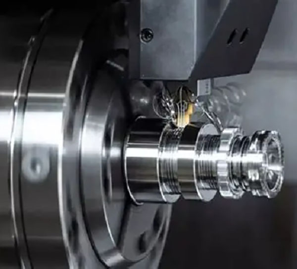
2. Five-axis linkage machining center: a sharp tool for processing complex curved surfaces
The five-axis linkage machining center can complete the machining of complex curved parts at one time through the coordinated movement of three linear axes of X, Y, and Z plus two rotary axes of A and C, without the need for multiple clamping. Its core advantage over three-axis machines is that it can process parts that cannot be reached by three-axis machines, such as impellers and mold cavities, with more than 60% fewer clamping times and positioning errors reduced to ±0.005mm. For example, in the prototype processing of aero engine blades, the five-axis linkage technology can control the processing accuracy of the blade surface to ±0.01mm, meeting the stringent requirements of the aviation level.
3. Micro-milling features below 0.1mm: the path to achieve microscopic accuracy
For machining tiny features below 0.1mm (such as micro gear tooth thickness, medical catheter interface), it is necessary to solve core problems such as tool rigidity and cutting vibration. In actual combat, it is necessary to use ultra-fine tungsten steel tools with a diameter of ≤0.1mm, with a high-rigidity machine tool (spindle runout ≤0.002mm), the cutting speed is controlled at 15000-30000rpm, and the feed rate is as low as 0.001mm/tooth. Through this solution, a precision instrument manufacturer successfully processed a prototype of a micro gear with a tooth thickness of 0.08mm, which met the miniaturization needs of smart wearable devices.
4. Aluminum 6061 Prototype Cutting Parameters: Golden ratio for precision machining
Aluminum 6061 is a popular material for prototyping due to its lightweight and ease of cutting, and its optimal cutting parameters need to be adjusted according to the equipment and tool:
| Processing method | Cutting speed (m/min) | Feed (mm / tooth) | Depth of Cutting (mm) |
| rough machining | 300-500 | 0.2-0.3 | 1-3 |
| Finishing | 600-800 | 0.05-0.1 | 0.1-0.5 |
| Key principles: high speed and low feed during finishing can reduce surface burrs; During rough machining, the cutting depth is appropriately increased to improve efficiency. |
5. Tolerance ±0.01mm Implementation method: multi-dimensional precision control
To achieve a high precision with a tolerance of ±0.01mm, it is necessary to start from four aspects: (1) Equipment selection: choose a high-precision CNC machine tool with a positioning accuracy ≤ 0.005mm; (2) Tool accuracy: use precision tools with cutting edge runout ≤ 0.003mm; (3) Process control: adopt the process of “roughing – stress relief heat treatment – semi-finishing – finishing”; (4) Real-time compensation: Through the online measurement system, the dimensional calibration is carried out every 5 pieces to compensate for the tool wear error. Through this method, a precision mold company stably controlled the tolerance of the injection mold insert prototype to ±0.008mm.
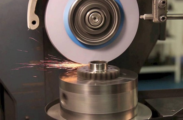
6. Surface Roughness Ra 0.8 Control Tips: Details determine quality
Surface roughness Ra 0.8 is a common requirement for prototypes, and the control core is: (1) Cutting parameters: cutting speed ≥ 600m/min during finishing, feed ≤ 0.1mm/tooth; (2) Tool status: replace the worn tool in time (must be replaced when the cutting edge wear > 0.02mm); (3) Cooling method: use high-pressure cooling oil (pressure ≥ 20bar) to avoid chips sticking to the tool; (4) Post-treatment: Chemical polishing can be used for aluminum parts, and fine grinding treatment can be used for steel parts.
7. The effect of stress-relieving heat treatment on deformation: eliminate hidden dangers in processing
In CNC machining, residual stresses inside the material can cause the workpiece to deform after machining. Stress relief heat treatment (such as 2 hours of insulation of aluminum parts at 200°C and 4 hours of insulation at 600°C for steel parts) can release more than 80% of the residual stress and reduce the amount of deformation in subsequent processing by 70%. A prototype processing case of an aviation aluminum 7075 bracket shows that when stress relief is not done, the flatness error after processing reaches 0.15mm. After heat treatment, the flatness error is controlled within 0.03mm.
8. 50% reduction in machining cycle time: practical results of process optimization
A new energy company needs to process a prototype of a battery shell, and the original process takes 4 hours per piece. Through three major optimizations: (1) the cutting speed is increased from 300m/min to 600m/min by adopting high-speed cutting parameters; (2) Establish a standard fixture library, and shorten the clamping time from 20 minutes to 5 minutes; (3) Enable unattended processing at night to achieve 24-hour continuous production. The final processing cycle time was reduced to 2 hours/piece, increasing efficiency by 50% and increasing monthly production capacity from 300 to 600 pieces.
2. Material selection and application scenarios: scientific decision-making to adapt to needs
1. Aerospace Aluminum 7075 Prototyping: Strength in the Aviation Sector
With a tensile strength of more than 500MPa, 30% higher than aluminum 6061, and strong corrosion resistance, aviation aluminum 7075 is the material of choice for aerospace component prototyping. In the prototype processing of a UAV wing, the wing main beam made of aviation aluminum 7075 passed the 6G overload test, and the weight was 40% lighter than that of the steel prototype, fully meeting the lightweight and high-strength requirements of the UAV.
2. Medical Ti6Al4V Small-Batch Trial Production: Medical Safety Material Guarantee
Medical Ti6Al4V (titanium alloy) is highly biocompatible, non-cytotoxic, and has a tensile strength of up to 860MPa, making it suitable for prototyping implantable medical devices (e.g., orthopedic screws, heart stents). When a medical company tried to produce orthopedic bone plate prototypes in small batches, it selected medical Ti6Al4V material, which passed the ISO 10993 biocompatibility test after CNC machining, and the dimensional tolerance was controlled at ±0.02mm to meet the precise requirements of surgical implantation.
3. PEEK Plastic High Temperature Prototype: Resistant to extreme environments
PEEK plastics are resistant to high temperatures up to 260°C, chemical and mechanically strong, making them suitable for prototyping at high temperatures (e.g., automotive engine sensor housings, aviation hydraulic system components). When an automobile manufacturer developed a prototype of a turbocharger sensor, it was processed with PEEK plastic, which worked continuously for 1,000 hours in a high-temperature environment of 200°C, without deformation or aging, and its performance was better than that of traditional nylon materials.
4. Stainless Steel 316L Corrosion Resistance Test: A protective barrier for harsh environments
Stainless steel 316L contains molybdenum elements, which is 5 times more corrosive than 304 stainless steel, especially resistant to corrosion from seawater and acid-alkali solutions, and is often used in the prototyping of marine equipment and chemical instruments. When processing the seawater sensor housing prototype, a marine monitoring equipment company conducted a 1000-hour salt spray test on the stainless steel 316L prototype, and the surface was rust-free, meeting the 5-year service life requirement in the marine environment.
5. Magnesium alloy AZ91D lightweight solution: the optimal solution to weight reduction needs
Magnesium alloy AZ91D has a density of only 1.8g/cm³, which is 2/3 of aluminum and 1/4 of steel, and is close to aluminum 6061, making it suitable for making weight-sensitive prototypes (e.g., laptop cases, drone bodies). When a consumer electronics company developed a prototype of an ultra-thin notebook case, it was processed with magnesium alloy AZ91D, which weighed 25% less than the aluminum alloy prototype, and passed the 1.5-meter drop test, which was rigid.
6. Copper Electrode Rapid EDM Prototypes: Efficient tools for EDM
Copper electrodes have good electrical conductivity and low losses, making them a core material for rapid EDM (electrical discharge machining) prototypes. In the prototype processing of mold cavities, copper is used to make electrodes, and complex cavities can be quickly replicated through EDM processing, with a processing accuracy of ±0.01mm, an electrode loss rate of ≤3%, which is 40% higher than that of graphite electrode processing, which is suitable for the rapid production of small-batch mold prototypes.
7. Carbon Fiber Composite Clamping Process: Fixing techniques for difficult-to-machine materials
Carbon fiber composites have high strength and brittleness, and are prone to delamination and chipping during processing, and the core of their clamping process is “flexible fixation + uniform stress”. In practice, the combination of vacuum suction cup + elastic briquetting is used, the suction cup pressure is controlled at 0.05-0.1MPa, and the contact area of the briquetting block is ≥5cm² to avoid material damage caused by excessive local pressure. An aerospace company used this process to process carbon fiber wing skin prototypes, without delamination or chipping after processing, and the dimensional tolerance was controlled at ±0.03mm.
8. Material cost and performance trade-off table: a reference basis for rational selection
| material | Tensile Strength (MPa) | Density (g/cm³) | Temperature Resistance (°C) | Cost per piece (yuan / piece) | Applicable scenarios |
| Aluminum 6061 | 276 | 2.7 | 120 | 50-100 | General prototypes, structural parts |
| Aerospace Aluminum 7075 | 503 | 2.8 | 150 | 150-300 | aviation, high-strength structural parts |
| Medical Ti6Al4V | 860 | 4.5 | 310 | 800-1500 | Medical implants, high-precision components |
| PEEK plastic | 90 | 1.3 | 260 | 200-500 | High-temperature, corrosion-resistant components |
| Stainless steel 316L | 515 | 7.9 | 870 | 100-200 | Corrosion resistant, outdoor equipment |
| Magnesium alloy AZ91D | 230 | 1.8 | 120 | 200-400 | Lightweight, consumer electronics components |
3. Cost structure and cost reduction strategy: practical skills for careful budgeting
1. CNC Prototype Cost Per Piece Calculator: Break down the cost makeup with clarity
CNC prototype cost per piece = material cost + equipment depreciation + labor cost + tool loss + auxiliary material cost + overhead expense, the specific calculation logic:
- Material cost: material weight × unit price (e.g. aluminum 6061 unit price 20 yuan/kg, part weight 0.5kg, material cost 10 yuan);
- Equipment depreciation: total machine tool price ÷ service life ÷ annual processing volume (such as 1 million machine tool used for 10 years, 10,000 pieces processed per year, depreciation cost 10 yuan / piece);
- Labor cost: × hourly wage for operating hours (such as 1 hour of processing, 50 yuan per hour, labor cost 50 yuan);
- Tool loss: The total tool price ÷ the number of machined pieces (e.g., 100 yuan for 20 pieces, the loss cost is 5 yuan/piece).
Through this calculator, the cost of a single piece can be quickly calculated, providing data support for quotation and cost reduction.
2. Bulk ladder quotation 1/10/50 pieces: cost advantage of scale effect
Mass production can significantly reduce unit costs, taking aluminum 6061 parts as an example, the tiered quotation pattern is as follows:
| Batch (Piece) | Cost per piece (yuan) | Total Cost (RMB) | Unit cost decrease |
| 1 | 150 | 150 | – |
| 10 | 100 | 1000 | 33.3% |
| 50 | 70 | 3500 | 53.3% |
| Core reason: Batch machining can reduce the number of clamping, optimize cutting parameters, and reduce tool sharing costs, which is suitable for scenarios where design verification has been completed and small-batch trial production is required. |
3. Optimize tool life and tool change frequency: Extend the tool life cycle
Tool loss is one of the core components of cost, and the optimization strategies include: (1) selecting coated tools (such as TiAlN coating), which can extend the tool life by 2-3 times compared to uncoated tools; (2) Match the cutting parameters to avoid overheating and wear of the tool caused by excessive cutting speed; (3) The tool wear monitoring system is used to replace the tool in time when the wear amount reaches 0.02mm to avoid the scrapping of the workpiece due to tool failure. A machine shop used this strategy to increase the life of carbide tools from 50 to 120 pieces per bar, reducing tool costs by 58%.
4. Feasibility of unattended processing at night: an invisible weapon to release production capacity
To achieve unattended processing at night, three conditions need to be met: (1) Equipment stability: the trouble-free operation time of the machine tool ≥ 8 hours; (2) Program reliability: the processing code has been verified by simulation, and there is no risk of collision; (3) Monitoring system: equipped with tool wear monitoring, workpiece size detection, and abnormal alarm device. A precision parts factory has increased machine utilization from 60% to 90%, increasing monthly production capacity by 50% without additional labor costs.
5. Design for Manufacturing 10 Guidelines: Reduce costs at the source
Following DFM (Design for Manufacturing) guidelines can significantly reduce machining costs:
- Avoid internal deep cavities (depth > 5 times the diameter) to reduce the input of special tools;
- Adopt a uniform hole diameter to reduce the number of tool changes;
- avoid sharp angles, and use R≥0.5mm rounded corners to reduce tool loss;
- Simplify the structure of parts and reduce the processing process;
- reserve a reasonable clamping position to avoid secondary clamping;
- Tolerance requirements match functions, no need to pursue high precision;
- Use standard materials to avoid the high cost of special materials;
- Reduce thin-walled structure (thickness < 1mm) to avoid processing deformation;
- Symmetrical structure is designed for easy processing and detection;
- Reserve processing allowance to avoid scrapping due to insufficient allowance.
6. Outsourcing vs. own equipment break-even point: the basis for scientific decision-making
when the annual processing volume < X, outsourcing is more cost-effective; When the annual processing volume is >X, it is more economical to have your own equipment. The formula for calculating the break-even point X is: X = (total equipment price + annual maintenance fee) ÷ (outsourcing unit price – in-house processing unit price). For example, if the total price of equipment is 1 million, the annual maintenance fee is 100,000 yuan, the outsourcing unit price is 200 yuan/piece, and the unit price of self-owned processing is 80 yuan/piece, then X=(1 million + 100,000)÷(200-80)≈9167 pieces. If the annual processing volume ≥ 10,000 pieces, it is recommended to purchase its own equipment; If < 8,000 pieces, outsourcing has a cost advantage.
7. Express proofing 48-hour delivery premium: a solution for urgent needs
For urgent R&D projects, the 48-hour express proofing service can meet the needs of rapid verification at a premium of 100%-200%. For example, the unit price of an aluminum prototype delivered in 3 days is 100 yuan, and the unit price of 48 hours delivery is 250 yuan. Suitable scenarios: exhibition sample urgency, customer emergency verification, R&D project node sprint. It is recommended to choose regular delivery for non-urgent projects, balancing cost and efficiency.
4. Quality inspection and risk control: the whole process of quality assurance
1. 100% 3-coordinate full inspection process: the ultimate check of dimensional accuracy
The coordinate measuring instrument can achieve high-precision inspection of three-dimensional dimensions, and the 100% full inspection process includes: (1) Workpiece cleaning: remove surface oil stains and chips; (2) Benchmark calibration: take the part design reference as the measurement standard; (3) Measuring point planning: 3 key dimension measurement points ≥ 2 non≥-critical dimension measurement points; (4) Data collection: measurement speed ≤ 5mm/s to avoid vibration affecting accuracy; (5) Report generation: compare design drawings and mark the excess items. A precision electronics company used this process to reduce the prototype size defect rate from 3% to 0.5%.
2. Closed-loop compensation for online laser measurement: real-time correction of processing errors
The online laser measurement system detects the workpiece size in real time during the machining process and corrects the tool path through a closed-loop compensation algorithm. Its working principle: The laser sensor measures the actual size once for every feature point processed, and if there is an error (e.g. + 0.008mm), the system automatically adjusts the tool feed (0.008mm) to ensure accurate subsequent machining dimensions. After adopting this technology, the machining error was reduced from ±0.015mm to ±0.005mm.
3. Tip wear prediction algorithm: avoid machining risks in advance
By monitoring the three core parameters of cutting force, spindle vibration, and cutting temperature, the wear state of the tool tip can be predicted. When the cutting force suddenly increases by 20%, the vibration frequency exceeds 50Hz, and the temperature exceeds 200°C, it indicates that the wear of the tip is about to exceed the standard, and the system will issue an alarm and prompt for tool replacement. A prediction algorithm developed by a machine tool factory with an accuracy rate of 92% can provide 10-minute warning to avoid workpiece scrap due to tool failure.
4. Dimensional change of aluminum parts after anodizing: precision control of surface treatment
When aluminum parts are anodized, an oxide film of 5-20μm forms on the surface, resulting in an increase in size (typically 10-15μm), which directly affects tolerance accuracy. The control strategy includes: (1) Machining reserve allowance: reserve a single side allowance of 10-15μm during CNC machining according to the oxide film thickness; (2) Hard anodizing: if a thicker oxide film (≥20μm) is required, it can be processed to close to the final size, and then finely ground after oxidation; (3) Dimensional compensation design: clearly mark the “post-oxidation size” in the drawings, and include the oxide film thickness into the design tolerance. When processing an aluminum shell prototype for a communication equipment company, by reserving a 12μm allowance, the dimensional tolerance after oxidation is stable at ±0.01mm, which fully meets the assembly requirements.
5. Internal Stomatal X-ray CT Screening: Gain insight into internal defects
For prototypes that require high reliability (e.g., aero engine components, medical implants), defects such as internal porosity and cracks may lead to service failure. X-ray CT screening enables non-destructive testing with an accuracy of 0.01mm, providing a clear picture of the location, size, and shape of internal defects. Screening process: (1) Workpiece fixation: use special fixtures to fix to avoid displacement during testing; (2) Parameter setting: voltage 120-150kV, current 50-100μA, scanning resolution 5-10μm; (3) Image analysis: reconstruct the 3D model by CT software, identify defects and grade (A-grade: no defects; Class B: Defect ≤0.02mm, acceptable; Grade C: Defect >0.02mm, need to be reworked). An aviation parts company conducted CT screening on the prototype of titanium alloy blades and successfully detected three internal pores of 0.03mm, avoiding subsequent installation risks.
6. First article inspection report template download: standardize the inspection process
First article inspection is a key link before batch processing, which can detect problems such as design, procedure, and tool in a timely manner. The standard first article inspection report should include: (1) basic information (part name, drawing number, batch, processing date); (2) Inspection equipment (coordinate measuring instrument, hardness tester, etc.); (3) Dimensional inspection results (design value, measured value, deviation); (4) Appearance quality (surface roughness, burrs, scratches); (5) Performance test (hardness, tensile strength, etc., fill in as needed); (6) Inspection conclusion (pass/fail/concession acceptance); (7) Signature confirmation (inspector, technician, supervisor). Templates can be downloaded through industry platforms and adjusted according to enterprise needs to ensure standardized and traceable inspection processes.
7. Non-conforming product 8D Corrective Action: Closed-loop solution to quality problems
When there are non-conforming products, the 8D (Eight Disciplines) method can fundamentally solve the problem: (1) D1 set up a team: a special team composed of design, process, production, and quality inspection personnel; (2) D2 describe the problem: clarify the quantity, batch, and type of defect (such as dimensional deviation, surface scratches); (3) D3 Temporary measures: isolate unqualified products, avoid flowing into the next process, and suspend production if necessary; (4) D4 root cause analysis: through fishbone diagram and 5Why analysis method, find out the core causes (such as tool wear and program errors); (5) D5 Corrective actions: formulate plans for the root cause (such as tool replacement, optimization of procedures); (6) D6 verification effect: After the implementation of the measures, the inspection pass rate needs to be ≥ 99.5% for 3 batches of products to be processed continuously; (7) D7 Preventive measures: incorporate corrective actions into standard processes (such as increasing tool wear monitoring); (8) D8 Summary and archiving: record the whole process and update the work instructions. A machine shop passed 8D method, which solved the problem of over-dimensional stainless steel parts, and the failure rate was reduced from 5% to 0.3%.
8. Customer on-site acceptance checklist: Ensure delivery meets standards
Customer on-site acceptance is the final step in prototype delivery, and preparing a checklist in advance can improve acceptance efficiency. Core list: (1) Appearance quality: no burrs, scratches, oxidation color difference, surface roughness meets the requirements (such as Ra 0.8); (2) Dimensional accuracy: 100% detection of key dimensions, deviation ≤ tolerance range (such as ±0.01mm); (3) Performance test: Hardness, corrosion resistance, high temperature resistance and other tests are carried out on demand, and the results meet the standard; (4) Documents: provide the first inspection report, material certificate, processing process card, CT screening report (on demand); (5) Assembly verification: assembled with supporting parts, the mating clearance is ≤ 0.03mm, and there is no jamming. Check each checklist to ensure 100% customer satisfaction.
5. Moshijia Technology’s view
The core value of CNC prototype processing lies in “accurately matching R&D needs and balancing efficiency, cost, and quality”. In the current era of accelerated technological iteration, enterprises should not only focus on the optimization of a single indicator, but should build a full-process collaborative system: in terms of technology, through high-speed cutting, five-axis linkage and other technologies, break through the bottleneck of precision and efficiency; in terms of material selection, scientifically weigh performance and cost based on application scenarios; in terms of cost control, from the design source, production process, and equipment utilization to reduce costs in multiple dimensions; in terms of quality assurance, establish a closed-loop mechanism of “detection-early warning-correction”. Moshijia Technology has been deeply involved in CNC prototype processing for many years, always focusing on customer needs, integrating high-precision equipment, professional process teams, and standardized processes to provide customized solutions for aerospace, medical, consumer electronics, and other fields. We firmly believe that only by combining technical depth, industry experience and service awareness can we truly help customers shorten the R&D cycle, reduce market risks, and seize opportunities in the fierce competition.
6. FAQ
1. What is the minimum tolerance for CNC prototype machining?
Currently, mature CNC prototype machining in the industry has a minimum tolerance of ±0.005mm, which requires high-precision five-axis machine tools, precision tools, and online compensation systems, making it suitable for scenarios with high precision requirements, such as aerospace and medical. The recommended tolerance for conventional prototype machining is ±0.01-±0.05mm, taking into account both accuracy and cost.
2. How to choose the right material for prototyping?
Priority is given to screening according to application scenarios: (1) Aviation and high-strength requirements: choose aviation aluminum 7075 and titanium alloy Ti6Al4V; (2) High temperature and corrosion resistance requirements: choose PEEK plastic and stainless steel 316L; (3) Lightweight requirements: choose magnesium alloy AZ91D, aluminum 6061; (4) Medical implants: Medical Ti6Al4V must be selected, and biocompatibility test reports must be provided. At the same time, refer to the cost of materials and the difficulty of processing to avoid excessive pursuit of high performance and cost waste.
3. What are the conditions for unattended processing at night?
The core conditions include: (1) Equipment stability: machine tool MTBF (mean time between failures) ≥ 8 hours, equipped with automatic chip removal device; (2) Program reliability: the processing code has been simulated and verified by UG, Mastercam and other software, and there is no risk of collision or overcut; (3) Monitoring system: install tool wear monitoring, size online detection, abnormal alarm (SMS / APP notification) equipment; (4) Safety guarantee: equipped with fire prevention and oil leakage prevention devices, and set emergency stop buttons.
4. What scenarios is 48-hour express proofing suitable for?
Suitable for urgent R&D needs: (1) Expedited exhibition samples (need to quickly make display prototypes); (2) Customer emergency verification (sample confirmation is required in a short period of time); (3) R&D node sprint (avoid project stagnation due to prototype delays). Note: The 48-hour delivery premium is high (100%-200%), and only supports simple structural parts, which cannot be met by prototypes with complex surfaces and multi-process machining.
5. How can I control the dimensional change of aluminum parts after anodizing?
Key measures: (1) Reserve the margin of oxide film thickness during processing (usually 10-15μm on one side); (2) Choose the appropriate oxidation process (ordinary oxide film thickness 5-10μm, hard oxide film thickness 15-25μm); (3) If higher precision is required after oxidation, fine grinding or polishing can be carried out; (4) Clearly mark the “final size after oxidation” in the design drawings to avoid misunderstandings caused by unclear labeling.