Learn how to master thread milling with our ultimate step-by-step CNC guide. Discover expert tool selection, path formulas, and troubleshooting tips.
1. Thread Milling Fundamentals
What is helical interpolation?
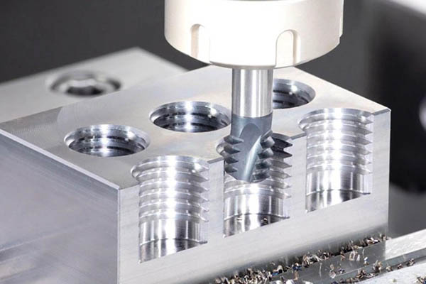
Thread milling is a modern CNC machining method to cut internal or external threads. Unlike old tools, a thread mill moves along three axes at the exact same time. The tool rotates on its own spindle axis. Meanwhile, it travels in a circular path along the X and Y axes. At the same time, it moves slowly along the Z axis. This combined movement is called helical interpolation.
One complete 360-degree circle in X and Y matches a vertical move in Z. This vertical move must equal exactly one thread pitch. By using this precise path, the tool cuts highly accurate threads in a single pass or multiple passes. It does not bind or clog. This makes it much safer than traditional techniques.
Thread milling versus tapping
Many machine shops struggle to choose between tapping and thread milling. Tapping is fast and simple. However, it carries major risks. If a tap breaks, it jams deep inside the hole. Removing a broken tap can ruin an expensive workpiece. This is a common issue when working with hard materials like titanium or stainless steel.
In contrast, a thread mill has a smaller diameter than the hole. If the tool breaks, it does not get stuck. You can easily lift the broken pieces out. This saves the part from being scrapped. Also, you can use a single tool to cut different thread diameters, as long as they share the same pitch. Tapping requires a unique tool for every single size. The table below compares these two popular methods.
| Feature | Tapping (Cut or Form) | Thread Milling |
| Tool broken risk | High. Hard to remove without damage. | Low. Easy to remove from hole. |
| Thread size flexibility | Fixed. One tool per thread size. | High. One tool fits multiple diameters. |
| Machining hard metals | Difficult. High risk of tool breakage. | Excellent. Low cutting pressure. |
| Blind hole clearance | Requires deep clearance at bottom. | Can cut very close to the bottom. |
| Pitch limits | Locked to tool design. | Locked to tool pitch design. |
2. Selection Guide for Tools
Comparing tool styles
Selecting the right tool style is critical for successful thread milling. The three main options are single-profile, multi-profile, and indexable insert thread mills. Each type fits specific production volumes and budgets.
- Single-profile tools: These tools have a single cutting tooth. They are highly versatile. You can use them to cut different pitches and sizes. However, they require more helical passes, which increases cycle times. Use them for short runs or prototype parts.
- Multi-profile tools: These tools feature multiple rows of cutting teeth. They can machine the full length of the thread in just one circular pass. This makes cycle times extremely short. They are perfect for high-volume manufacturing.
- Indexable insert tools: These tools use replaceable carbide inserts. The tool body lasts a very long time. When the cutting edge wears out, you only replace the insert. This is highly cost-effective for large threads above 20 mm in diameter.
Matching coatings and materials
Tool materials and coatings protect against heat and wear. Most thread mills are made of solid sub-micron carbide. This material offers high rigidity and resists deflection. For soft metals like aluminum, an uncoated tool or a DLC (Diamond-Like Carbon) coating works best. It prevents the metal from sticking to the cutting edges.
For steel and stainless steel, choose AlTiN (Aluminum Titanium Nitride) or TiAlN coatings. These coatings handle high temperatures well. They allow you to run at faster spindle speeds. For superalloys, use advanced silicon-based coatings to extend tool life.
3. Pre-Machining Setup Steps
Confirming thread details
Before you begin thread milling, you must know your exact thread specifications. Check the thread standard, major diameter, minor diameter, and pitch. For example, in an M10 x 1.5 thread, the major diameter is 10 mm, and the pitch is 1.5 mm. Ensure your program matches these dimensions perfectly. Any error here will cause the finished thread to fail inspection with a thread gauge.
Sizing pre-drilled holes
The pre-drilled hole size determines the minor diameter of an internal thread. If the hole is too small, the thread milling tool will experience excessive load and might break. If the hole is too large, the thread will be weak. Always use standard engineering charts to choose the correct drill bit. For a standard 65% or 75% thread depth, use the formula:
$$\text{Drill Size} = \text{Major Diameter} – \text{Pitch}$$
For an M10 x 1.5 thread, the pre-drill diameter should be 8.5 mm. Ensure the drilled hole is straight and deep enough. You must leave room for any chips that fall to the bottom of the hole.
Evaluating machine stiffness
Helical interpolation demands high machine accuracy and rigidity. Your CNC mill must support smooth, synchronized three-axis movement. If your machine has backlash in the ball screws, it will cut oval or distorted threads. Always use a high-quality spindle with minimal runout. Keep runout below 0.01 mm to ensure even load distribution across all cutting teeth.
4. Internal Thread Milling Steps
Step 1: Set position
Start by programming the thread milling tool to move above the hole center. This is your safe starting point. Rapid down along the Z-axis to the target depth. For internal threads, it is usually best to start from the bottom of the hole and cut upward. This is called climb milling. It produces clean chips and a great surface finish.
Step 2: Enter path
Do not plunge the tool straight into the metal wall. This sudden shock will chip the carbide teeth. Instead, use a smooth arc entry path. This is known as a radial entry arc or roll-on path. The tool should travel along a 90-degree or 180-degree arc to gently touch the wall. This smooth path gradually increases the chip load on the teeth.
Step 3: Cut thread
Once the tool contacts the metal, start the full 360-degree helical move. The tool travels in a circle while moving up along the Z-axis by exactly one thread pitch. For a right-hand internal thread, use counter-clockwise circular interpolation (G03 code) combined with upward Z travel. Keep the feed rate steady to avoid tool deflection.
Step 4: Exit path
After completing the full circle, use a smooth exit arc. This is the roll-off path. It mirrors the entry path. The tool moves away from the thread wall along a curve toward the center of the hole. This prevents tool marks on your fresh threads. Once in the center, safely retract the tool out of the hole at a rapid speed.
Step 5: Check size
Measure the completed thread using a calibrated thread go/no-go gauge. If the gauge is tight, do not panic. Do not change the physical tool. Instead, use your CNC control panel to adjust the tool wear offset. Increase the tool offset slightly to make the tool cut a fraction deeper, then run the program again.
5. External Thread Milling Steps
Preparing outer diameter
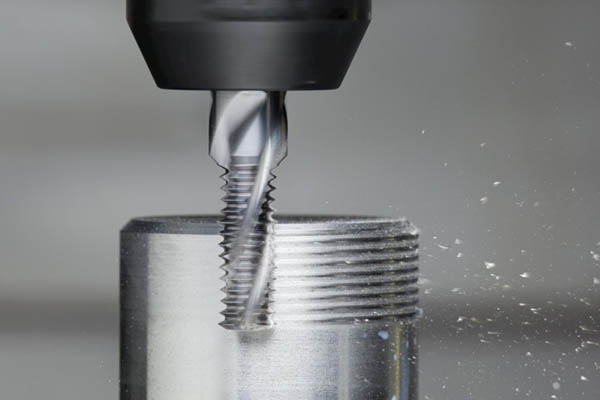
For external threads, the workpiece starts as a cylinder. You must pre-machine this outer diameter to the correct size. Turn or mill the cylinder to the major diameter of your thread. It is highly recommended to cut a small chamfer at the start of the cylinder. A 45-degree chamfer helps the thread mill enter smoothly and removes sharp burrs.
Adjusting tool path
The tool path for external threads is different from internal threads. The tool moves around the outside of the workpiece. You should still use climb milling. To cut a right-hand external thread, the tool moves clockwise around the cylinder. It starts from the top and moves downward along the Z-axis. Use a clean arc to approach the part, circle it, and then arc away.
Removing sharp burrs
External threading often leaves thin, sharp burrs at the top and bottom of the thread. You can clean these up easily. Run a quick light turning or milling pass over the outer diameter after threading. This cuts away the loose metal and leaves a clean, professional finish.
6. Speeds and Feeds Calculation
Choosing parameters by material
Different materials require different cutting speeds and feed rates. Harder metals require slower speeds to protect the tool. Softer materials allow faster speeds but require good chip control. The table below lists starting recommendations for common materials.
| Material Type | Cutting Speed (SFM) | Cutting Speed (m/min) | Feed Per Tooth (IPT) | Feed Per Tooth (mm/tooth) |
| Aluminum Alloys | 600 – 1200 | 180 – 360 | 0.002 – 0.005 | 0.05 – 0.12 |
| Carbon Steels | 300 – 500 | 90 – 150 | 0.001 – 0.003 | 0.02 – 0.08 |
| Stainless Steel (304/316) | 150 – 300 | 45 – 90 | 0.001 – 0.002 | 0.02 – 0.05 |
| Titanium Alloys | 80 – 150 | 24 – 45 | 0.001 – 0.002 | 0.02 – 0.05 |
Calculating correct feed rates
When programming a CNC machine for thread milling, you must adjust the feed rate. Most CNC controllers calculate the feed rate at the center of the tool. However, the cutting edge is at the outer diameter of the tool.
For internal threads, the tool path at the center is much smaller than the actual thread diameter. If you do not compensate, the actual feed rate at the cutting edge will be too high. This will overload and break your tool. Use the following formula to calculate the corrected internal feed rate:
$$F_{\text{actual}} = F_{\text{tool\_center}} \times \left( \frac{D_{\text{thread}} – D_{\text{tool}}}{D_{\text{thread}}} \right)$$
Calculation Example: M12 x 1.75 Thread in Steel
Let us walk through a real-world calculation. We want to cut an M12 thread using a solid carbide 8 mm thread mill with 4 flutes.
- Step 1: Calculate Spindle Speed (RPM). Standard cutting speed for steel is 120 m/min.$$\text{RPM} = \frac{120 \times 1000}{\pi \times 8} \approx 4,775\text{ RPM}$$
- Step 2: Calculate Linear Feed Rate ($F_{\text{tool\_center}}$). We choose a feed of 0.04 mm per tooth.$$F_{\text{tool\_center}} = 4,775 \times 4 \times 0.04 = 764\text{ mm/min}$$
- Step 3: Calculate Corrected Internal Feed Rate ($F_{\text{actual}}$).$$F_{\text{actual}} = 764 \times \left( \frac{12 – 8}{12} \right) = 764 \times 0.333 = 254.6\text{ mm/min}$$
Result: Program 254.6 mm/min in your CNC control. This keeps the actual chip load safe and prevents tool failure.
7. Quality Check and Troubleshooting
Using thread gauges
Always inspect your finished work. Use a standard thread plug gauge for internal threads. The “Go” side must screw in smoothly by hand without forcing. The “No-Go” side must not enter more than two full turns. For external threads, use a thread ring gauge in the same way.
Solving common problems
If you encounter issues, refer to the troubleshooting guide below to find quick solutions.
| Symptom | Root Cause | Recommended Action |
| Chipped tool teeth | Feed rate is too high; tool is plunging directly. | Reduce feed rate; use a smooth arc entry path. |
| Tapered thread | Tool deflection under heavy cutting load. | Use two or three passes; check tool rigidity. |
| Poor surface finish | Recutting chips; bad coolant flow. | Increase coolant pressure; use air blast for dry cuts. |
| Threads too tight | Tool wear; incorrect tool offset. | Adjust wear offset in CNC controller. |
8. Advanced Tips and Best Practices
Using multi-pass strategies
For hard materials, do not try to cut the full depth of the thread in a single pass. This puts too much pressure on the tool. Instead, use a multi-pass strategy. Cut 70% of the depth on the first pass, and the remaining 30% on the second pass. This reduces tool deflection and ensures perfectly straight, highly accurate threads.
Choosing proper coolants
Good chip evacuation is critical. If chips stay in the hole, the tool will recut them, leading to immediate tooth chipping. Use high-pressure flood coolant to wash chips out of the hole. For aluminum, a rich water-soluble oil works best. For steels, use neat cutting oil or a strong synthetic coolant. For dry machining, use a strong air blast to blow chips away.
Frequently Asked Questions
- Can I use a thread mill to cut different thread sizes?Yes. As long as the threads share the exact same pitch, you can use the same tool. You only need to change the diameter settings in your CNC program.
- Why is climb milling preferred over conventional milling?Climb milling creates a chip that starts thick and thins out. This transfers the heat into the chip instead of the workpiece, protecting the tool edge and yielding a cleaner surface finish.
- What should I do if my thread is tapered?Taper happens when the tool deflects. To fix this, split the cutting depth into two passes or use a thicker, shorter tool body to increase rigidity.
- How do I prevent tool breakage in blind holes?Ensure the hole is drilled deeper than the required thread length to allow chips to settle at the bottom. Use high-pressure coolant to clear chips instantly.
Get projects quote with Moshijia Technology
Need high-precision threaded components with zero defects? Moshijia Technology provides professional CNC machining, expert thread milling, and rapid prototyping services. Contact our engineering team today to get an instant quote and technical support for your next project.