Need a CNC milling part that fits perfectly and performs reliably? We break down the milling process, materials, tolerances, design tips, and how to avoid costly mistakes.
Introduction
You have a design. It is sitting in your CAD software. Maybe it is a bracket. Maybe it is a housing. Maybe it is something nobody has built before. Now you need to turn that screen image into a real object that you can hold in your hand.
That is where CNC milling parts come in.
Milling is the most versatile machining process on the planet. It takes a solid block of material and removes everything that does not look like your part. The result is a precision component ready for assembly.
But here is the thing—not all milled parts are created equal. The difference between a part that works and a part that fails comes down to design choices, material selection, and the shop you choose to build it.
This guide covers everything you need to know. We explain how milling works, what materials machine best, how tight tolerances can go, and exactly how to design parts that are easy to make and hard to break.
What Is a CNC Milling Part?
Let us define the term clearly. A CNC milling part is any component manufactured using a computer-controlled milling machine. The process removes material from a solid workpiece using rotating cutting tools.
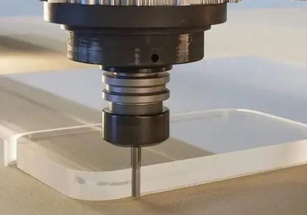
Think of it like this: You start with a block of metal or plastic. The machine spins a cutter at high speed. It moves that cutter through the material along precise paths. When the program finishes, what remains is your part.
Milled parts share some common characteristics:
- They have flat surfaces, pockets, and holes
- They feature complex 3D contours
- They include precise details like threads and chamfers
- They meet tight dimensional tolerances
A simple CNC milling part might be an aluminum mounting bracket with four holes. A complex one could be a five-axis machined titanium housing for a medical device with internal passages and compound angles.
The beauty of CNC milling is flexibility. Change the program, and you change the part. No special tooling required beyond standard cutters.
How Does CNC Milling Work?
Understanding the process helps you design better parts. Here is what happens inside that enclosed machine.
The Machine Setup
A CNC milling machine has several key components:
- The spindle: Holds and spins the cutting tool
- The table: Holds the workpiece in place
- The axes: Move the tool or table in multiple directions
- The controller: Reads G-code and moves the axes accordingly
Basic machines offer three axes: X (left-right), Y (front-back), and Z (up-down). Advanced machines add rotary axes—A, B, and C—allowing the tool or part to tilt and rotate.
The Cutting Action
The milling cutter rotates at high speed—often 8,000 to 20,000 RPM for aluminum, slower for steel. As it spins, it moves through the material, shearing off tiny chips.
Two main types of milling exist:
Face milling cuts flat surfaces with the end of the tool. Think of creating a smooth top surface on a block.
Peripheral milling cuts with the sides of the tool. This creates walls, slots, and complex profiles.
Toolpaths and Strategy
Modern CAM software generates toolpaths that balance speed and precision. Roughing passes remove bulk material quickly. Finishing passes take light cuts to achieve final dimensions and surface finish.
A real example: A job shop needed to mill an aluminum enclosure with thin walls. The first attempt used conventional toolpaths. Thin walls deflected during cutting, causing taper. The fix? High-efficiency roughing with constant tool engagement and reduced radial cuts. Walls came out straight, cycle time dropped by 30%.
What Materials Can Be Milled?
CNC milling works with almost any solid material. Here is how common options compare.
Metals
| Material | Machinability | Typical Applications |
|---|---|---|
| Aluminum 6061 | Excellent | Brackets, housings, prototypes |
| Aluminum 7075 | Good | Aerospace, high-stress parts |
| Mild Steel | Good | Machine components, fixtures |
| Stainless Steel 304 | Fair | Medical, food contact, marine |
| Stainless Steel 17-4 | Good | Aerospace, high-strength parts |
| Titanium Grade 5 | Fair | Aerospace, medical implants |
| Brass | Excellent | Fittings, decorative parts |
| Copper | Good | Electrical components, heat sinks |
Plastics
| Material | Machinability | Typical Applications |
|---|---|---|
| Delrin (POM) | Excellent | Gears, bushings, precision parts |
| Nylon 6/6 | Good | Wear parts, guides |
| PTFE (Teflon) | Fair | Seals, chemical-resistant parts |
| PEEK | Good | High-temperature, medical, aerospace |
| Acrylic | Good | Transparent parts, displays |
| Polycarbonate | Good | Impact-resistant parts |
Material Selection Tips
Pick material based on function, not just cost. A CNC milling part that lives indoors can use 6061 aluminum. The same part in a marine environment needs 5052 or 316 stainless.
A medical device company learned this lesson. They prototyped a surgical tool handle in 6061. Worked great. For production, they switched to 17-4 stainless for sterilization compatibility. The material change required new feeds, speeds, and tooling—but the part performed perfectly through hundreds of autoclave cycles.
How Tight Can Tolerances Get?
Tolerances determine how precisely a part must match its drawing. Tighter tolerances cost more. Here is what is achievable.
Standard Tolerances
Most machine shops hold ±0.005 inches (0.13 mm) without breaking a sweat. This covers holes, pocket depths, and feature locations. For critical fits, specify tighter.
Precision Tolerances
With good equipment and careful setup, ±0.001 inches (0.025 mm) is routine. Bores that must locate bearings, shafts that press into housings—these need this level.
High-Precision Tolerances
Some shops achieve ±0.0002 inches (0.005 mm) on critical features. This requires temperature-controlled environments, specialized tooling, and meticulous process control. Expect to pay for it.
Tolerance Comparison Table
| Tolerance Class | Value (inches) | Value (mm) | Typical Application |
|---|---|---|---|
| Loose | ±0.010 | ±0.25 | Non-critical clearance holes |
| Standard | ±0.005 | ±0.13 | Most features, general machining |
| Precision | ±0.001 | ±0.025 | Bearing fits, mating surfaces |
| High-Precision | ±0.0002 | ±0.005 | Hydraulic spools, critical alignments |
An aerospace supplier needed a CNC milling part with a 0.0005 inch tolerance on a bore diameter. They tried three shops. Two failed. The third succeeded by using a boring head with micron adjustment, measuring every tenth part, and compensating for tool wear in real time. The parts passed first article inspection.
What Equipment Is Needed?
Producing quality milled parts requires the right machines and tools.
CNC Milling Machines
3-axis mills handle most work. They are cost-effective and widely available. The workpiece stays fixed while the tool moves in X, Y, and Z.
4-axis mills add rotation around one axis. This allows machining cylindrical features or indexing to different faces without re-clamping.
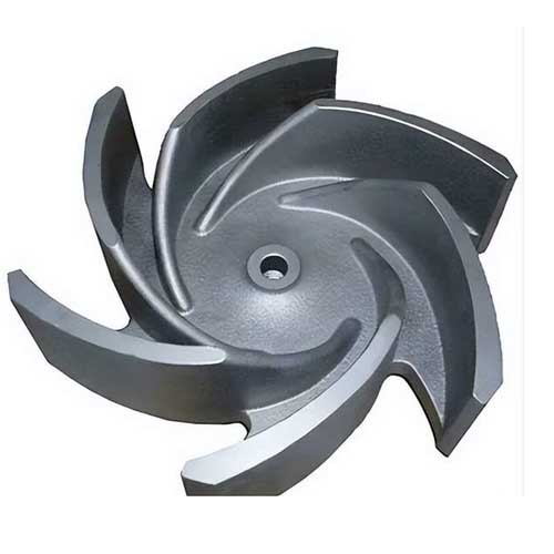
5-axis mills add two rotary axes. They machine complex shapes in a single setup. Impellers, turbine blades, and medical implants benefit from 5-axis capability.
Cutting Tools
End mills come in many flavors:
- Square end: Creates flat bottoms and vertical walls
- Ball end: Creates 3D contours and radii
- Corner radius: Strengthens the tool tip, reduces chipping
- Drills: Create holes
- Reamers: Size holes precisely
- Thread mills: Cut internal or external threads
Workholding
The part must stay still during cutting. Common methods include:
- Vises: Quick and versatile
- Fixtures: Custom-made for specific parts
- Vacuum chucks: Hold thin parts flat
- Double-sided tape: Works for prototypes
Inspection Equipment
You cannot trust what you cannot measure. Good shops use:
- Calipers and micrometers for basic checks
- CMM (Coordinate Measuring Machine) for complex geometries
- Optical comparators for profiles
- Surface roughness testers for finish requirements
How to Design for Milling?
Good design makes good parts. Follow these rules to ensure your CNC milling part comes out right.
Avoid Deep, Narrow Pockets
Deep pockets need long tools. Long tools deflect. Deflection causes taper and poor finish.
Rule: Keep depth less than 4 times tool diameter when possible.
Add Radii to Internal Corners
Square corners need square tools. Square tools leave radiused corners equal to the tool radius.
Rule: Design inside corners with a radius. Match it to common tool sizes—1/8″, 3/16″, 1/4″.
Watch Wall Thickness
Thin walls vibrate during cutting. Vibration causes chatter and dimensional errors.
Rule: Keep walls above 0.040 inches for metals, 0.060 inches for plastics. Thicker is better.
Design for Standard Tool Sizes
Shops stock common end mill diameters. Using odd sizes means special orders and higher cost.
Rule: Design holes and features around fractional inch or metric standard sizes.
Consider Tolerances Strategically
Tight tolerances cost time and money. Only specify them where function demands.
Rule: Put tight tolerances on mating features. Let everything else run standard.
A startup learned this lesson painfully. They designed a drone motor mount with ±0.001 inch on every dimension. Quote came back at $800 per part. They revised the drawing—tight tolerances only on bearing pockets and mounting holes. New quote: $180 per part. Same function. Lower cost.
Where Are Milled Parts Used?
CNC milling parts appear everywhere in modern industry.
Aerospace
Aircraft use thousands of milled components. Seat tracks, bracket assemblies, wing ribs, engine mounts. Materials range from aluminum to titanium to Inconel. Weight savings drive every decision.
Automotive
From prototype intake manifolds to production suspension components, milling delivers. Racing teams machine custom parts for every race. Production vehicles use milled transmission housings and engine blocks.
Medical
Surgical instruments, implant trials, and device housings come from milling machines. Biocompatible materials like titanium and PEEK are common. Surface finish and cleanliness matter greatly.
Electronics
Heat sinks, enclosures, and chassis parts protect sensitive components. Aluminum is the go-to material. Anodized finishes add protection and style.
Industrial Equipment
Machine guards, fixtures, and replacement parts keep factories running. Many shops maintain their own milling capabilities for quick repairs.
Consumer Products
Bicycle components, camera bodies, audio equipment—high-end consumer goods often feature milled parts. The machined look signals quality and precision.
Conclusion
CNC milling parts form the backbone of modern manufacturing. The process transforms solid blocks into precision components that drive aerospace, medical, automotive, and consumer products.
Understanding how milling works helps you design better parts. Choosing the right material ensures performance. Specifying realistic tolerances controls cost. Working with a knowledgeable shop turns your CAD files into real hardware.
Whether you need one prototype or ten thousand production parts, milling delivers. The technology is mature. The processes are proven. The results speak for themselves.
Frequently Asked Questions
What is the difference between CNC milling and turning?
Milling uses rotating cutting tools on a stationary workpiece to create complex shapes. Turning rotates the workpiece against a stationary tool to create cylindrical features. Many parts require both operations.
How much does a CNC milled part cost?
Cost depends on material, complexity, quantity, and tolerance requirements. Simple aluminum parts can cost under $50 each in quantity. Complex five-axis titanium parts can run thousands. Getting a quote requires a CAD file and clear specifications.
What surface finish can I expect from milling?
Standard machined finishes range from 32 to 64 microinches Ra. Better finishes require finishing passes, smaller stepovers, and sometimes secondary operations like polishing or bead blasting.
Can you mill threads?
Yes. Thread milling uses a specialized tool that interpolates a helical path to cut threads. This works better than tapping for large diameters, hard materials, and blind holes where chip evacuation matters.
How long does CNC milling take?
Cycle time varies widely. A simple bracket might take 10 minutes. A complex aerospace part could run for hours. Setup time adds to overall lead time. Most shops quote delivery in days or weeks, not hours.
What file formats do machine shops need?
Most shops accept STEP files for geometry and PDF drawings for specifications. STEP files transfer solid models cleanly between different CAD systems. Some also accept native formats like SolidWorks, Fusion 360, or AutoCAD.
Get projects quote with Moshijia Technology.
Ready to machine your next part? At Moshijia Technology, we specialize in producing high-quality CNC milling parts for prototypes and production runs. Our 3-axis, 4-axis, and 5-axis CNC centers handle complex geometries with precision.
We work with all common materials—aluminum, steel, stainless, titanium, and engineering plastics. We help you optimize designs for manufacturability. We inspect every critical feature and deliver parts that meet your specifications.
Upload your CAD file today. Get a quote within 24 hours. Let’s build something great together.