Navigating the world of light part CNC machining presents a unique set of challenges and opportunities for engineers and manufacturers. Whether you’re developing components for aerospace applications, advanced robotics, or next-generation consumer electronics, the demand for high-strength, lightweight parts is skyrocketing. This isn’t just about removing material; it’s a sophisticated dance of physics, material science, and precision engineering. From combating tool deflection and workpiece vibration to maintaining dimensional stability in thin-walled structures, success hinges on a deep understanding of the entire process chain. This guide, crafted from real-world experience, will walk you through the critical considerations—from material selection and fixturing to cutting parameters and post-processing—to help you consistently produce flawless, high-tolerance lightweight components.
What Defines a “Light Part” in CNC Machining?
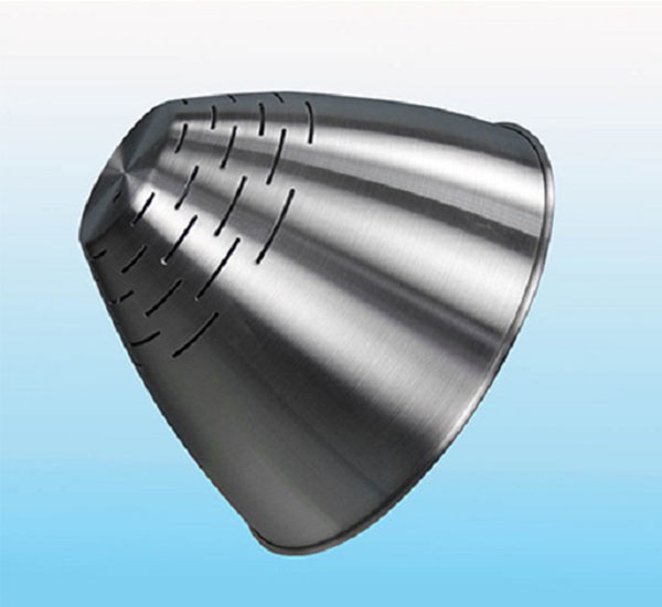
In CNC machining, a “light” or “delicate” part isn’t defined solely by weight. It’s characterized by low structural rigidity and a high sensitivity to machining forces. Think of a part where the wall thickness is less than 1 mm, or where the aspect ratio (height to thickness) of a feature is exceptionally high. These parts lack the innate stiffness to resist the pressures exerted by cutting tools and fixturing without bending, vibrating, or warping.
Common examples from our shop floor include:
- Aerospace Bracket: An aluminum 7075 bracket with 0.8 mm walls, designed to hold avionics.
- Medical Device Casing: A magnesium alloy housing for a portable scanner, featuring intricate lattices.
- Drone Arm: A carbon fiber-reinforced polymer (CFRP) arm with internal ribbing for stiffness.
The primary challenge shifts from simply shaping the material to preserving its geometric integrity throughout the process. Every decision, from the first clamping touch to the final cut, must be made with its fragility in mind.
Which Materials Work Best for Lightweight Components?
Material choice is the foundational decision for any lightweight CNC part. The ideal material offers an excellent strength-to-weight ratio while maintaining good machinability.
| Material | Key Properties | Best For | Machinability Notes |
|---|---|---|---|
| Aluminum Alloys (6061, 7075) | High strength-to-weight, excellent machinability, good thermal conductivity. | Aerospace frames, drone components, enclosures. | The industry benchmark. 7075 is stronger but slightly less machinable than 6061. |
| Titanium Alloys (Ti-6Al-4V) | Exceptional strength-to-weight, corrosion resistance, biocompatible. | Medical implants, aerospace structural parts, high-performance racing. | Challenging: low thermal conductivity causes heat buildup, requires sharp tools and lower speeds. |
| Magnesium Alloys | The lightest structural metal, good damping capacity. | Camera housings, laptop chassis, aerospace components. | Highly flammable in chip form—requires specific safety protocols and dry machining often preferred. |
| Engineering Plastics (PEEK, Delrin) | Lightweight, corrosion-resistant, electrical insulators. | Insulators, bearings, low-friction components. | Prone to elastic deformation during cutting; require razor-sharp tools and rigid setups. |
| Composites (CFRP, GFRP) | Extreme stiffness-to-weight ratio, customizable properties. | Aerospace panels, sporting goods, automotive bodies. | Abrasive and anisotropic (cuts differently with fiber direction); cause rapid tool wear. |
Pro Tip: For prototypes or parts not requiring extreme strength, consider machineable foams (like REN Shape) for ultra-light, complex geometries.
What Are the Key Challenges in Machining Delicate Parts?
Machining light parts amplifies common CNC challenges. The top three hurdles are:
- Vibration and Chatter: A thin wall acts like a tuning fork. Tool vibration or workpiece chatter leads to poor surface finish, tool breakage, and out-of-tolerance dimensions.
- Thermal Deformation: The minimal mass of a light part cannot dissipate heat effectively. Heat buildup from cutting can cause localized expansion and permanent warping upon cooling.
- Elastic Deformation: The part can temporarily bend away from the tool during cutting due to cutting forces, a phenomenon known as “pushing off.” When the tool passes, the material springs back, resulting in inaccurate dimensions and wall thickness variation.
A real case: We once machined a large, thin aluminum diaphragm. Initial runs showed a 0.15 mm taper across the surface—the part was literally being pushed down by the tool pressure. The solution involved a multi-pronged approach: switching to a sharper tool geometry, reducing radial depth of cut, and implementing adaptive toolpaths that engaged the material more consistently.
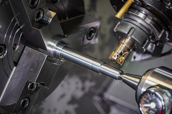
How Does Tool Selection Impact Light Part Quality?
Your tool is the surgeon’s scalpel. For light parts, tool geometry is more critical than ever.
- End Mills: Use sharp, polished flutes with high helix angles (40°+). This design shears the material cleanly and efficiently pulls chips up and out, reducing recutting and heat. For finishing thin walls, long-reach, tapered neck end mills provide increased rigidity compared to straight tools.
- Tool Material: Micro-grain carbide offers the best blend of hardness and toughness. For highly abrasive composites, diamond-coated tools are essential for longevity.
- Diameter: Smaller diameters (e.g., 3mm or 1/8″) reduce tool pressure, but they also deflect more. The key is to use the largest possible tool diameter that the geometry allows to maximize stiffness.
- Count: A 3-flute end mill often provides the ideal balance for aluminum—more rigid than 2-flute, with better chip evacuation than 4-flute in non-ferrous materials.
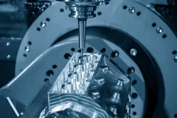
What Cutting Parameters Prevent Deformation?
The classic “hogging out material” approach will destroy a delicate part. The strategy shifts to high-speed, low-force machining.
- Speed (RPM): Higher spindle speeds are your friend. They allow you to maintain a good surface speed while using a lighter chip load.
- Feed Rate: Maintain a consistent and appropriate chip load. Too low, and you rub and generate heat; too high, and you increase deflection. Use chip-thinning calculations for small stepovers.
- Depth of Cut: Employ a trochoidal or adaptive milling strategy. These toolpaths use a small radial engagement (e.g., 5-10% of tool diameter) with a full axial depth. This spreads heat along the tool’s length and dramatically reduces side-force on the part.
- Climb Milling vs. Conventional: Always use climb milling (where the cutter rotates with the feed direction). This technique pulls the workpiece into the cutter, reducing the “push-off” effect and providing a cleaner cut.
Which Fixturing Strategies Secure Fragile Workpieces?
If the part moves or flexes in the vise, all other optimizations are wasted. Fixturing must hold securely without distorting the part.
- Soft Jaws & Custom Fixtures: Machine soft aluminum jaws to cradle the part’s specific geometry, distributing clamping force over a larger area.
- Vacuum Chucks: Excellent for large, flat, thin parts like panels. They provide even, distributed holding force across the entire back surface. Ensure the seal is good and the pump provides sufficient vacuum level.
- Low-Melt Alloys (e.g., CerroTrue): For bizarrely shaped or ultra-fragile parts, you can cast the workpiece into a block of this alloy for total support, then melt it away after machining.
- Strategic Support: For long, cantilevered features, use temporary, machinable support structures (like bridges or tabs) that are removed in a final operation.
How Can You Achieve Tight Tolerances on Thin Walls?
Holding a ±0.025 mm tolerance on a 0.5 mm wall is the pinnacle of light part CNC machining.
- Sequential Roughing & Finishing: Leave a uniform stock allowance (e.g., 0.2 mm) after roughing. Use a separate, sharp finishing tool with optimized parameters to remove this final material in one calm, continuous pass.
- Temperature Control: Machine in a climate-controlled environment. For critical parts, let the workpiece normalize to room temperature between operations. Use coolant at ambient temperature, not chilled, to avoid thermal shock.
- Spring Passes: Program a final “spring pass”—an identical finishing pass with no additional material removal—to clean up any residual deflection from the first pass.
What Role Does Coolant Play in Light Part Machining?
Coolant serves two vital functions: heat removal and chip evacuation.
- Flood Coolant: Effective at heat control and washing away chips. However, the force of the fluid stream can sometimes vibrate a very thin wall.
- Mist Coolant (MQL): Minimum Quantity Lubrication is often superior for light parts. It delivers a precise aerosol of lubricant directly to the cutting edge, providing cooling and lubrication with minimal fluid force on the workpiece.
- Dry Machining: Sometimes necessary (e.g., with magnesium). Requires perfect chip evacuation and careful monitoring of heat, often achieved through very high speeds and tiny chip loads.
How Do You Balance Speed vs. Precision?
This is the core trade-off. Pushing for speed increases forces and heat, risking part failure. Going too slow induces rubbing and vibration.
The Solution: Optimize for Precision First, Then Speed. Dial in your parameters for a perfect, scrapless finish on a single part. Then use the following levers to increase speed without sacrificing quality:
- Increase spindle speed (RPM).
- Use adaptive toolpaths to maintain optimal chip load at higher feed rates.
- Optimize toolpath efficiency to reduce non-cutting air time.
- Consider using a faster machine if part volume justifies it—a machine with a 30k+ RPM spindle and high acceleration will outperform a standard machine dramatically.
What Post-Processing Steps Enhance Final Results?
The journey doesn’t end when the machining stops.
- Deburring: Use manual, non-abrasive methods like scraping or cryogenic deflashing for delicate edges. Avoid aggressive media tumbling.
- Stress Relieving: For parts that have undergone significant material removal, a low-temperature thermal stress relief cycle can stabilize the part and prevent future distortion.
- Surface Finishing: Vibratory finishing with gentle media or hand polishing can improve surface finish and fatigue resistance without removing critical material.
- Cleaning: Ultrasonic cleaning is highly effective for removing chips and coolant from intricate, lightweight components.
Conclusion
Successfully machining light parts is a testament to a machinist’s skill and a shop’s technological capability. It requires moving beyond standard practices and adopting a holistic philosophy focused on minimizing force, managing heat, and providing unwavering support. By meticulously selecting lightweight materials, employing sharp tools with high-speed toolpaths, utilizing intelligent workholding solutions, and controlling the environment, you can transform the challenge of delicate components into a reliable, high-precision process. Remember, the goal is to make the part feel as rigid as possible to the tool, through every strategic decision you make.
FAQ on CNC Machining Light Parts
What is the most common mistake in light part CNC machining?
Using tools and parameters designed for heavy stock removal. This applies excessive force, leading immediately to chatter, deflection, and scrap parts. Always start with a “light touch” philosophy.
Can I machine light parts on a standard 3-axis CNC mill?
Absolutely. While 5-axis machines offer advantages for complex geometries, most lightweight component challenges are solved through tooling, parameters, and fixturing, not just machine axes. A rigid, well-maintained 3-axis mill is perfectly capable.
How thin of a wall is realistically achievable with CNC machining?
With specialized techniques, experienced shops can reliably machine wall thicknesses down to 0.2-0.3 mm in aluminum, and even thinner (0.1 mm) in certain plastics for small features. Success depends heavily on part geometry, material, and the strategies outlined above.
Is it more expensive to machine light parts?
Yes, typically. The process requires more engineering time (CAM programming), often more specialized tooling and fixturing, longer machining times due to lighter cuts, and a higher degree of operator skill and attention. This is reflected in the cost.
What file format is best when submitting a design for a light part quote?
Always provide a 3D model (STEP or IGES preferred) in addition to 2D drawings. This allows the manufacturer to fully analyze the geometry for potential issues with thin walls, deep pockets, and fixturing early in the process.
Get a Quote for Your Precision Light Part Project
Pushing the boundaries of lightweight design requires a manufacturing partner that understands the nuances of high-precision, delicate CNC machining. At Moshijia Technology, we combine decades of engineering expertise with state-of-the-art equipment to transform your most challenging designs into reality.
We specialize in:
- Advanced Materials: From aluminum and titanium to engineered plastics and composites.
- Complex, Low-Rigidity Geometries: Thin walls, deep pockets, and intricate features.
- Extreme Tolerances: Holding critical dimensions to within microns.
- End-to-End Support: From design-for-manufacturability feedback to final post-processing and inspection.
Ready to see if your project is a fit? Upload your drawings or 3D models for a confidential, detailed quote. Let’s build something remarkable, together.
Get projects quote with Moshijia Technology.