Master thread milling with this step-by-step guide. Learn to choose the right tools, program perfect helical paths, avoid tool breakage, and hit exact tolerances.
Every CNC machinist knows the dread of a broken tap. You have a high-value workpiece. It is almost finished. You run a hard-metal tap into a deep hole, and it snaps. Now, you have to burn out the carbide or scrap the entire part.
This is why thread milling is a game changer. It is safer, more flexible, and highly precise. Unlike tapping, a thread mill does not get stuck. If a thread mill breaks, it does not lock itself into the hole. You can easily remove the broken tool and save your workpiece.
But thread milling comes with its own challenges. The programming is more complex. You have to handle helical motion. You must select the right tool, calculate the correct feed rates, and manage chip removal. If you set the parameters incorrectly, you will get tapered threads, poor surface finish, or quick tool wear.
This practical guide gives you five essential tips to master thread milling. These tips will help you improve your setups, get perfect thread quality, and extend your tool life.
1. Choose the Right Thread Mill
Selecting the correct tool is your first step. The wrong cutter will cause deflection or slow down your cycle time. You must balance versatility against production speed.
Solid Carbide vs. Indexable Inserts
Solid carbide thread mills offer the highest rigidity. They have precise geometries and sharp edges. This makes them perfect for small holes, hard materials, and high-precision parts. They can easily cut threads below M6.
Indexable insert thread mills use steel bodies with replaceable carbide inserts. They are great for larger holes, usually over 12mm ($0.5″$). They save you money on high-volume runs. You only replace the cheap carbide insert, not the entire tool body. However, the steel body is less rigid than solid carbide. You must watch out for tool deflection on deep threads.
Single-Point vs. Multi-Profile Tools
Single-point thread mills have a single cutting tooth profile. They are highly versatile. One tool can cut different thread pitches and diameters. They exert very low cutting pressure on your machine spindle and workpiece. This makes them ideal for long-reach applications or thin-walled parts. The downside is cycle time. You have to program multiple helical passes to cut the full depth of the thread.
Multi-profile thread mills have several rows of cutting teeth. They cut the entire thread depth in a single 360-degree helical pass. This makes them extremely fast. They are the best choice for mass production. However, they create high cutting forces. If your machine setup is not highly rigid, multi-profile tools will deflect and create a tapered thread.
| Tool Type | Best Application | Pros | Cons |
| Solid Carbide | Small holes, hard materials, high precision | Very rigid, very sharp, highly accurate | High upfront cost, cannot replace inserts |
| Indexable Insert | Large holes ($>12\text{ mm}$), high volume | Low cost per edge, versatile tool bodies | Lower rigidity, not for tiny holes |
| Single-Point | Long reach, unstable setups, custom pitches | Low cutting force, highly versatile | Slow cycle times, needs multiple passes |
| Multi-Profile | Mass production, short threads, rigid setups | Extremely fast, cuts full depth in one pass | High cutting force, prone to deflection |
2. Set Correct Cutting Parameters
You cannot guess your speeds and feeds. Thread milling uses intermittent cutting. The teeth enter and exit the material rapidly. This creates heat and mechanical shock. You must use precise calculations.
Calculate Cutting Speed and Feed
Start with your manufacturer’s recommended surface speed ($V_c$). Calculate your spindle speed ($n$) using standard formulas.
Next, find your linear feed rate. You must start with the correct feed per tooth ($f_z$). If your feed per tooth is too small, the tool will rub against the metal. Rubbing creates heat and work-hardens the material. This quickly ruins your carbide tool. If $f_z$ is too high, the teeth will chip.
Understand Radial Feed Compensation
This is where many CNC programmers make a critical mistake. They program the tool feed rate at the center of the spindle ($F_{\text{centre}}$). But the actual cutting happens at the outer diameter of the tool ($F_{\text{edge}}$).
When you mill an internal thread, the tool path center is much smaller than the actual thread diameter. The tool center travels a shorter distance than the cutting edge. If you do not compensate, your actual cutting feed rate at the edge will be way too high. This will instantly snap your tool.
You must use this internal radial compensation formula to find the correct center feed rate:
$$F_{\text{centre}} = F_{\text{edge}} \times \frac{D_{\text{hole}} – D_{\text{tool}}}{D_{\text{hole}}}$$
For external threads, the center path is larger than the outer path. Use this external compensation formula:
$$F_{\text{centre}} = F_{\text{edge}} \times \frac{D_{\text{workpiece}} + D_{\text{tool}}}{D_{\text{workpiece}}}$$
Most modern CNC controllers can calculate this automatically if you use tool radius compensation (G41 or G42). If your control does not support this, you must calculate the adjusted feed rate in your CAM software.
Plan Your Multi-Pass Strategy
Do not try to cut the full thread depth in one pass when working with tough metals like stainless steel, titanium, or Inconel. Use a multi-pass strategy.
A multi-pass strategy breaks the radial depth of cut into smaller steps. This reduces cutting forces and prevents tool deflection. For hard steels, use three to four passes. Make your first pass the deepest, and use a small finish pass of about 0.05mm ($0.002″$) to get a perfect surface finish.
3. Optimize Your Tool Path
The way your tool enters, cuts, and leaves the material dictates your thread quality. Bad tool paths cause chatter marks, tool damage, and poor thread forms.
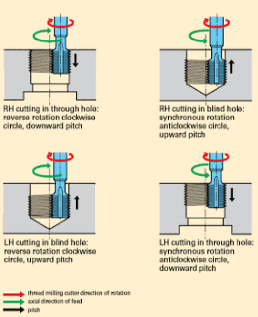
Master Helical Interpolation Moves
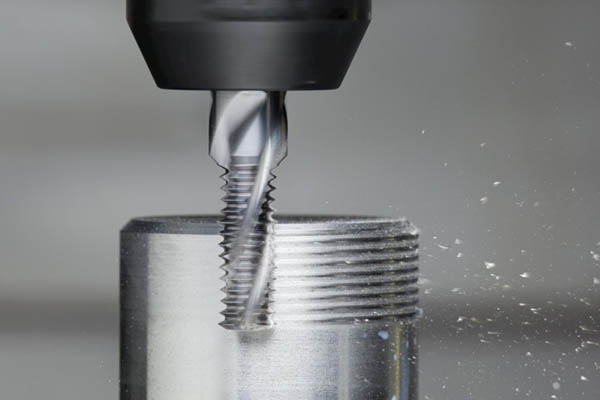
Thread milling relies on helical interpolation. The machine moves three axes simultaneously. The X and Y axes move in a circle while the Z-axis moves axially by one thread pitch per 360-degree turn.
For right-hand internal threads, you have two choices:
- Start at the bottom of the hole and feed upward.
- Start at the top of the hole and feed downward.
Feeding from the bottom up is usually the best approach. It allows you to use climb milling easily while moving away from the chips at the bottom of the hole.
Always Choose Climb Milling
Always use climb milling (G41) instead of conventional milling (G42). In climb milling, the tool cuts thick chips first and exits on thin chips. This directs the cutting heat into the chips rather than the workpiece. It reduces work-hardening and gives you a much cleaner thread finish. Conventional milling will drag the tool teeth, causing chatter and premature tool failure.
Use Arc Roll-In Entry
Never plunge your thread mill directly into the metal along a straight line. This sudden impact will chip your carbide teeth. Instead, use an arc roll-in (radial lead-in) tool path.
The tool should travel in a smooth 90-degree or 180-degree arc to enter the cut. This gradually increases the chip load from zero to your target feed rate. When the cut is finished, use an arc roll-out (radial lead-out) to exit the material smoothly. This prevents any exit marks or burrs on your threads.
4. Ensure Rigidity and Evacuation
Even with perfect programming, a flimsy setup or trapped chips will ruin your threads. You must control physical vibration and clear out debris.
Minimize Tool Overhang Ratio
Rigidity is everything in metal cutting. Keep your tool overhang as short as possible. Use the shortest tool that can reach your target thread depth.
The tool deflection increases dramatically with length. Specifically, deflection is proportional to the cube of the tool overhang length ($L^3$). If you double your tool length, your tool will deflect eight times more under the same cutting force!
Always use high-quality tool holders. Hydraulic chucks, shrink-fit holders, or high-precision ER collet chucks offer the best concentricity and gripping force. Avoid standard side-lock Weldon holders. They push the tool to one side, which introduces runout. Runout causes uneven tooth loading, leading to chipped teeth and poor thread quality.
Clear Chips with Coolant
In thread milling, chip evacuation is critical. This is especially true for internal blind holes. If your tool recuts loose chips, it will chip its edges and ruin the thread profile.
Use high-pressure coolant or a strong air blast to blow chips out of the hole. For steel and aluminum, high-pressure through-spindle coolant is the best option. It flushes the chips directly up and out of the cavity. For dry-machining materials or cast iron, use a compressed air blast to clear the hole.
5. Verify and Inspect Quality
The final step is checking your work. You must verify that your CNC program and tool offsets produce threads that fit perfectly.
Perform a Scrap Trial Cut
Never run your new program directly on your expensive, finished workpiece. Always run a trial cut on a piece of scrap metal of the exact same material first.
This test run lets you check your G-code for errors. It also lets you verify that your spindle speed, feed rates, and entry arcs are working smoothly without any chatter noises.
Measure with Thread Gauges
Once your trial part is cut, inspect the threads. Do not rely on a standard bolt to check your threads. Use calibrated thread go/no-go gauges.
- The Go gauge must screw in smoothly through the entire depth of the thread. If it binds, your thread pitch diameter is too small.
- The No-Go gauge must not enter the thread. If it screws in more than two turns, your thread pitch diameter is too large.
Apply Radial Wear Compensation
If your Go gauge does not fit because the thread is too small, do not panic. This is normal tool deflection. You do not need to rewrite your G-code.
Use your CNC controller’s radial wear compensation (D-value). Adjust your tool offset diameter slightly. Make a small adjustment—for example, $0.02\text{ mm}$ ($0.0008″$)—and run the tool path again. This radial fine-tuning will cut the thread to its exact target tolerance without changing your coordinates.
Thread Milling FAQ
Can I cut different thread sizes with the same thread mill?
Yes. If you use a single-point thread mill, you can cut any thread size with the same pitch. For example, you can cut an M12x1.5 and an M16x1.5 thread with the exact same tool. You only need to adjust the circular diameter in your CAM program.
Why is my thread mill breaking inside blind holes?
The most common cause is chip packing. Chips settle at the bottom of the hole, and the tool recuts them. Make sure you use through-spindle coolant or a strong air blast. Also, leave a gap of at least 2 to 3 thread pitches of extra depth at the bottom of your blind hole so chips have space to collect.
How do I fix tapered threads?
Tapered threads happen when the tool deflects under cutting pressure. To fix this, use a multi-pass strategy instead of cutting the thread in a single pass. You can also use a more rigid tool holder, reduce your feed per tooth ($f_z$), or program a “spring pass” (a zero-depth finish pass that cleans up any deflection).
Is thread milling faster than tapping?
Generally, tapping is faster in terms of raw cycle time, especially in soft materials like aluminum. However, thread milling is faster when you calculate the total cost of production. Thread mills run at higher surface speeds and do not break easily. They can also chamfer and mill the thread in a single tool setup, saving you cycle and tool-change time.
Get projects quote with Moshijia Technology
Need high-precision CNC threaded parts? At Moshijia Technology, our expert product engineers utilize advanced CNC machines and optimal thread milling strategies to deliver perfect tolerances and finishes. Contact us today to get a fast, professional quote for your next rapid prototyping or custom manufacturing project!