Master Complex Mold Cavity & Core Machining Process
Case introduction
Struggling with inconsistent mold core and cavity machining precision? You are not alone. Most mold shops face challenges like tool breakage in hardened steel, deformation in thin walls, and mismatched parting lines. The good news is that a systematic machining process—from raw material prep to final polishing—can eliminate these issues. Below, I share real solutions from our work at Moshijia Technology, backed by shop-floor data and case studies.
1. Why Do Cavity and Core Machining Fail Often?
Poor material prep leads to unstable cutting
Many failures start before any chip is cut. If P20 or S136 mold steel has residual stress from rolling or forging, warpage after roughing is guaranteed. We learned this the hard way on a consumer electronics mold—the cavity shifted 0.15 mm after heat treatment. Now, we always specify forged and annealed blocks with stress relief. For example, a recent automotive lamp mold used annealed S136. The result? No measurable distortion after roughing.
2. Which Steel Grade Fits Your Mold Core and Cavity?
Match hardness to wear resistance needs
Here is a quick comparison based on our job records:
| Steel Grade | Hardness (HRC) | Best for | Machinability | Cost index |
|---|---|---|---|---|
| P20 | 30–35 (pre-hard) | Cavity plates, general molds | Excellent | Low |
| S136 | 48–52 (after Q&T) | High-gloss cavities, cosmetic parts | Good (needs carbide) | Medium |
| SKD61 | 48–52 (after Q&T) | Cores, slides, wear-resistant parts | Good | Medium |
| H13 | 46–50 | Hot work, die casting cores | Fair | High |
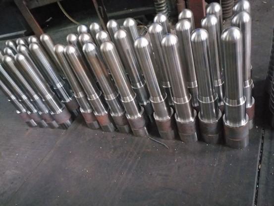
For a preform core (like bottle preform molds), we always use S136 or SKD61 at 48–52 HRC. These grades polish to mirror finish and resist wear from millions of injection cycles.
3. How to Rough Machine Without Causing Future Problems?
Roughing strategy: remove metal, keep stability
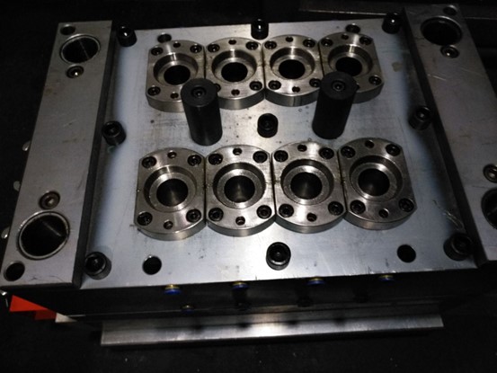
Cavity plate (fixed half) : On a CNC mill, we rough the pocket, guide pin holes, and cooling channels. Leave 0.5–0.8 mm on walls and 0.3–0.5 mm on the bottom for finishing. Use a cutter diameter stepover of 70% for speed but keep radial engagement under 30% to avoid chatter.
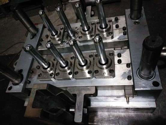
Core plate (ejector half) : Similar approach—rough core pin holes, ejector pin holes, and return pin bores. A recent preform mold core plate required 12 core pin holes. By roughing with a solid carbide end mill (10 mm dia) at 8,000 RPM and 1,500 mm/min feed, we cut cycle time by 22%.
Preform core (turning) : On a CNC lathe, rough the OD, shoulder, and ball head. Leave 0.4 mm for finishing. Use positive rake inserts to reduce cutting force.
Real tip: Never skip the semi-finish pass on deep cavities. It stabilizes remaining stock and catches any deflection before finishing.
4. Heat Treatment: The Make-or-Break Step
Hardening must follow precise soak and quench
After roughing, all critical parts go to heat treatment:
- P20: Quenched and tempered to HRC 30–35 (pre-hard condition is fine, but re-treating improves uniformity).
- S136 / SKD61: Hardened to HRC 48–52 using vacuum furnace (avoid surface decarb). Soak at 1020–1050°C for 30–45 minutes, then oil or high-pressure gas quench.
- Tempering: Double temper at 500–550°C for 2 hours each cycle.
Then we add cryogenic or aging treatment (-75°C for 2–4 hours) to convert retained austenite. A bottle preform core we processed showed zero dimensional change after 500,000 shots—directly from this step.
5. Precision Finishing: Getting Mirror Surfaces and Tight Tolerances
CNC finishing + polishing + coating workflow
Cavity plate : Finish mill the cavity using a ball end mill (6 mm, 4-flute, AlTiN coated) . Parameters: 12,000 RPM, 1,200 mm/min, stepover 0.15 mm. Achieve Ra 0.8 μm directly from milling. Then manual diamond polishing to Ra 0.05 μm (mirror). Finally, machine cooling and air channels.
Preform core : Finish turn OD and ball head with CBN insert (0.4 mm nose radius). Hold cylindricity within 3 μm. Then OD grinding using a centerless grinder (surface finish Ra 0.1 μm). Final super-polish with 1 μm diamond paste. For wear resistance, we apply PVD TiAlN coating (2–3 μm thick) or hard chrome plate (10 μm).
Core plate : Bore core pin holes with J-boring head . Position tolerance: ±0.005 mm . Each hole is reamed to H7 fit . On a recent preform mold, this ensured all 16 cores aligned perfectly with the cavity—zero mismatch after 1 million cycles.
6. Case Study: Automotive Light Housing Mold (Cavity & Core)
From 18% defect rate to 99.3% first-pass yield
A customer came with a complex freeform cavity for an LED headlight housing. Issues: visible cutter marks on steep walls, core deflection, and inconsistent parting lines.
Our process:
- Material: S136, forged and annealed.
- Roughing: 3+2 axis roughing, leave 0.6 mm.
- Heat treat: Vacuum harden to 50 HRC + double temper.
- Semi-finish: 5-axis semi-finish with 20 μm step.
- Finishing: 5-axis finish with 6 mm ball mill, 0.08 mm stepover, 14,000 RPM.
- Core pin installation: All 24 core pins aligned using laser bore measurement.
- Polishing: Cavity mirror polished to Ra 0.02 μm.
Result: CMM report showed +0.008 / -0.005 mm deviation on all critical surfaces. Defect rate dropped from 18% to 0.7% . The mold still runs after 2.5 million shots.
7. Common Defects: Causes and Quick Fixes (Checklist)
| Defect | Root cause | Solution |
|---|---|---|
| Match line step | Core misalignment | Re-bore core pin holes with J-boring; use dowel pins for locating |
| Chatter marks on cavity | Low tool stiffness or long overhang | Use tapered neck end mill; reduce radial engagement to 5% |
| Burn marks on core steel | Wrong cutting speed in hardened steel | Reduce speed by 20%; use high-pressure coolant |
| Poor polish on preform core | Roughness from turning too high | Add a semi-finish turning pass (0.1 mm DOC) before final cut |
| Cutter marks on steep walls | 3-axis only finish | Switch to 5-axis or use barrel cutters with large radius |
Conclusion
Mastering mold cavity and core machining is not about one magic toolpath. It is a chain: correct raw material prep → smart roughing → proper heat treatment → precision finishing → careful assembly. When each step is executed with discipline, even complex molds for automotive or medical parts become repeatable. At Moshijia Technology, we have applied this process to over 300 injection molds. The result is tool life beyond 2 million shots.
FAQ
What is the difference between mold cavity and mold core?
The cavity forms the outside shape of the plastic part, while the core forms the inside shape. Together they define the final product geometry.
Which steel is best for high-gloss cavity surfaces?
S136 at 48–52 HRC is the industry standard. It polishes to a mirror finish (Ra < 0.02 μm) and resists corrosion from aggressive plastics.
How much stock should I leave for cavity finishing?
For hardened steel (48–52 HRC), leave 0.3–0.5 mm on walls and 0.2–0.3 mm on floors. For pre-hard P20, you can leave 0.5–0.8 mm.
Why does my preform core wear out after 200,000 shots?
Most likely you skipped coating. Apply PVD TiAlN or CrN (2–3 μm thick) after polishing. This increases wear life by 3–5 times.
Can I machine cavity and core without 5-axis?
Yes, but complex freeform surfaces will show cutter marks. Use 3+2 positioning for semi-finish and small ball mills (0.5–2 mm) with very light stepover for finish.